6C13G11
6-16
1
2
3
4
5
6
7
8
9
Checking the lower case
1.
Check the skeg and torpedo for cracks or
damage. Replace the lower case if nec-
essary.
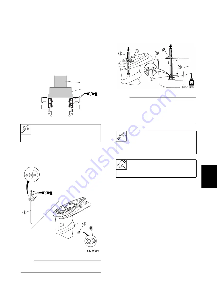
Assembling the oil seal housing
1.
Apply grease to new oil seals, and then
install them into the oil seal housing.
Assembling the lower case
1.
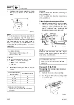
Install the shift rod assembly
1
and shift
cam
2
as shown.
NOTE:
Install the shift cam with the “UP” mark
a
facing upward.
2.
Install the needle bearing into the lower
case to the specified depth.
NOTE:
• Install the needle bearing with the manufac-
ture identification mark
b
facing up.
• When using the driver rod, do not strike the
special service tool in a manner that will
force the stopper
c
out of place.
Needle bearing attachment
1
:
90890-06653
Driver rod L3
2
: 90890-06652
S6C16200
A
A
2
1
Driver rod SL
3
: 90890-06602
Needle bearing attachment
4
:
90890-06614
Bearing depth plate
5
: 90890-06603
Depth
d
:
182.75
±
0.25 mm
(7.195
±
0.010 in)
Summary of Contents for F50F
Page 1: ...F50F FT50G F60C FT60D SERVICE MANUAL 6C1 28197 3G 11 290551 ...
Page 4: ......
Page 48: ...SPEC Specifications 2 25 6C13G11 MEMO ...
Page 190: ...LOWR Lower unit 6 47 6C13G11 Shimming FT50 FT60 6 ...
Page 195: ...6C13G11 6 52 1 2 3 4 5 6 7 8 9 MEMO Backlash FT50 FT60 ...
Page 221: ...6C13G11 7 24 1 2 3 4 5 6 7 8 9 Steering arm ...
Page 249: ...6C13G11 7 52 1 2 3 4 5 6 7 8 9 MEMO Power trim and tilt electrical system ...
Page 272: ...ELEC Electrical systems 8 21 6C13G11 MEMO ...
Page 301: ...6C13G11 i 5 1 2 3 4 5 6 7 8 9 Index MEMO ...
Page 303: ......
Page 304: ...YAMAHA MOTOR CO LTD Printed in the Netherlands Jul 2004 1 2 1 CR E_2 ...


