E
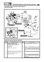
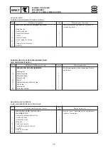
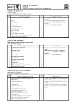
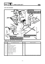
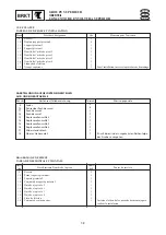
CARRYING HANDLE AND BOTTOM COWLING
BRKT
CARRYING HANDLE AND BOTTOM COWLING
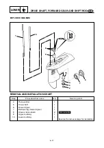
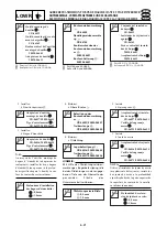
EXPLODED DIAGRAM
8
10
9
6
7
2
2
4
3
5
M6 x 25 mm
M6 x 25 mm
M6 x 16 mm
M6 x 16 mm
15
13
15
11
14
12
1
a
b
a
7-1
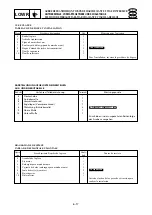
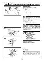
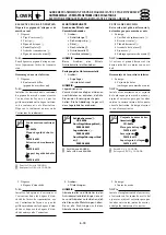
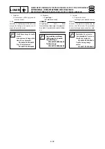
REMOVAL AND INSTALLATION CHART
Step
1
2
3
4
5
Q’ty
1
4
3
1
1
Service points
Follow the left ”Step” for removal.
Refer to ”INTAKE SYSTEM“ in chapter 4.
NOTE:
After installation, clamp the engine stop
switch lead to part 2 using the lead clamp
a
.
NOTE:
Clamp the hi-tension cord using the cord
clamp
b
, after the bottom cowling 2 has
been fitted.
Procedure/Part name
CARRYING HANDLE AND
BOTTOM COWLING REMOVAL
Top cowling
Choke wire
Engine stop switch lead
Bolt with washer (carrying handle 2)
Bolt with washer (bottom cowling 2)
Carrying handle2 (protector)
Bottom cowling 2

