background image

11

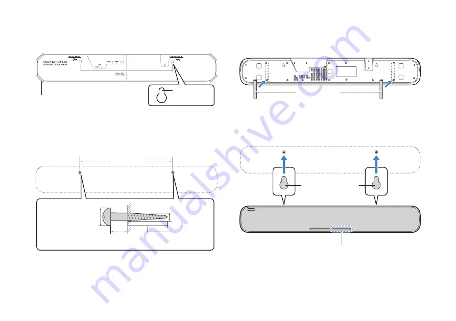
1. Attach the mounting template (supplied) on a wall and mark the 

two locations for the screw holes.

2. Remove the mounting template from the wall, and then install 

screws (sold separately) at the points marked on the wall.

3. Attach the supplied spacers to the bottom of the unit.

Peel off the backing from the spacer and press the adhesive part
against the bottom of the unit.

4. Hang the unit on the screws you installed.

Tape or thumbtacks

Mounting template

Screw holes

457 mm (18")

4 to 5 mm

Within 20 mm 
(3/4") or more

13 to 15 mm 
(1/2" to 5/8")

Diameter 7 to 9 mm 

(1/4" to 3/8")

Spacers

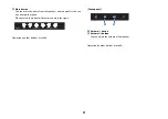
Touch panel

Mounting holes on the 

bottom of the unit

Summary of Contents for ESB-1090

Page 1: ...To use the unit safely and correctly be sure to read this guide with ESB 1090 Safety Brochure carefully before using it EN Front Surround System Owner s Manual...

Page 2: ...ions 12 1 Connecting a computer or AV device 12 2 Connecting a TV 12 3 Connecting an external subwoofer 13 4 Connecting the power cord 14 Mode of the unit 15 Types of modes 15 Setting the mode 16 Func...

Page 3: ...urround and DTS Virtual X are registered trademarks or trademarks of DTS Inc in the United States and or other countries DTS Inc All Rights Reserved The terms HDMI and HDMI High Definition Multimedia...

Page 4: ...This content indicates risk of serious injury or death CAUTION This content indicates risk of injury NOTICE Indicates content that you must observe in order to prevent the product from malfunctioning...

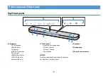
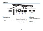
Page 5: ...URROUND indicator CLR VOICE indicator Additional indicator b Touch panel Input source setting button Volume button Volume button Power button NOTICE To prevent unintended operation do not place any ob...

Page 6: ...the Internet through a router with strong password protections Consult your router manufacturer for information on optimum security practices Use STP Shielded Twisted Pair cable to prevent electromagn...

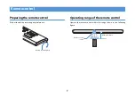
Page 7: ...out the battery insulating strip before use Operating range of the remote control Operate the remote control within the range shown in the following figure Remote control Battery insulating strip Rem...

Page 8: ...uct and keep it away from children The remote control supplied with this product contains a coin button cell battery If the coin button cell battery is swallowed it can cause severe internal burns in...

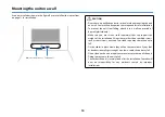
Page 9: ...ing it Doing so may damage the speakers or the portion covered with fabric When installing the unit do not stack with other equipment Doing so may cause a malfunction due to vibrations The unit contai...

Page 10: ...board Make sure you use screws sold separately that can support the weight of the installation Using clamps other than specified screws such as short screws nails and two sided tape may cause the unit...

Page 11: ...e wall 3 Attach the supplied spacers to the bottom of the unit Peel off the backing from the spacer and press the adhesive part against the bottom of the unit 4 Hang the unit on the screws you install...
Page 12: ...udio Return Channel ARC Use an ARC compatible HDMI cable sold separately and connect as shown in the figure NOTICE Use a 19 pin HDMI cable with the HDMI logo printed on it Keep the cable as short as p...

Page 13: ...any degradation in signal quality 3 Connecting an external subwoofer Use a mono pin cable sold separately and connect as shown in the figure NOTE Audio is output from both the unit s built in subwoof...

Page 14: ...power cord Connect the supplied power cord to the unit followed by the plug into the wall outlet When the plug is inserted into the wall outlet the unit will turn on The unit rear Power cord supplied...

Page 15: ...el mode The mode is for installing the unit in a hotel lobby or guest room and using it as a speaker for watching movies and TV programs or listening music Education mode This mode is for installing t...

Page 16: ...VOLUME button twice Press the mute button once Press TV button once When setting to Hotel mode Press INFO button once Press VOLUME button twice Press the mute button once Press HDMI button once When...

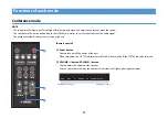
Page 17: ...nctions of each mode Remote control a Power button You can turn on off the power of the unit When turned on the STATUS indicator turns off and when turned off the STATUS indicator turns red b VOLUME b...

Page 18: ...e audio from the speakers and subwoofers You can also unmute the sound When muted the indicator flashes as shown in the figure Operation by other buttons is invalid Touch panel Operation by all button...

Page 19: ...to hear and play back human voices such as dialogues and narrations HDMI button You can set a computer or AV device connected to the HDMI IN jack as the input source of the audio signal TV button You...

Page 20: ...of indicator that lights up during adjustment h BASS EXT button You can enable disable the bass extension function a function that enhances bass sound for playback The indicator flashes three times wh...

Page 21: ...subwoofers You can also unmute the sound When muted the indicator flashes as shown in the figure Operation by other buttons is invalid Touch panel a Volume button b Volume button You can adjust the vo...

Page 22: ...a function that makes it easier to hear and play back human voices such as dialogues and narrations HDMI button You can set a computer or AV device connected to the HDMI IN jack as the input source o...

Page 23: ...t f BASS EXT button You can enable disable the bass extension function a function that enhances bass sound for playback The indicator flashes three times when it goes from disabled to enabled and once...

Page 24: ...24 Touch panel a Volume button b Volume button You can adjust the volume of the speaker Operation by other buttons is invalid b a...

Page 25: ...ol in the following order Press MUSIC button once Press VOLUME button twice Press the mute button once The unit will turn on 3 Press the power button on the remote control to turn off the unit 4 Press...

Page 26: ...XXXXXX Bluetooth XXXXX depends on the Bluetooth address from the list The unit and the Bluetooth device are paired and connected That s all for the procedure When the connection is completed the BLUET...

Page 27: ...Press VOLUME button twice Press the mute button once That s all for the procedure When the settings are completed the unit will turn on Function when the mode is canceled Remote control This is the sa...

Page 28: ...re When the switchover is complete the unit will turn on Bluetooth standby function You can use the Bluetooth standby function a function that allows you to operate the unit with a Bluetooth device Wh...

Page 29: ...e standby power consumption of the unit becomes larger than when it is disabled When both the Bluetooth standby function and the HDMI control function described on page 25 are disabled the STATUS indi...

Page 30: ...60 Hz U K Europe and Russia models AC100 V to 240 V 50 60 Hz Power consumption 30 W Rated Standby power consumption HDMI control off Bluetooth standby off 0 2 W HDMI control off Bluetooth standby on 1...

Page 31: ...5 1 channels Input jacks HDMI Digital optical 1 HDMI IN jack 1 TV jack Output jacks HDMI Analog RCA monaural 1 HDMI OUT ARC jack 1 SUBWOOFER OUT jack Other jacks USB Network ethernet 1 UPDATE ONLY ja...

Page 32: ...Hz 50 Hz 30 Hz 25 Hz 24 Hz Audio signals 2ch linear PCM 2 channels 32 kHz to 192 kHz 16 bit 20 bit 24 bit Multi ch linear PCM 6 channels 32 kHz to 192 kHz 16 bit 20 bit 24 bit Bitstream Dolby Digital...

Page 33: ...al Development Group Published 07 2021 Yamaha Global Site U S A and Canada https uc yamaha com Other countries https www yamaha com Yamaha Downloads U S A and Canada https uc yamaha com support Other...

Reviews: