54
DBR10/DBR12/DBR15
To debugging mode
To diagnosis mode
Is UART-0
connected?
YES
NO
Is debugging mode starting
switch turned on?
[POWER LED]turned on
[PROTECTION LED]
turned on
DSP initialized
(resetting cancelled)
(/DSP-RES)
ADC power down cancelled
(/AD-PDWN)
DSP boot • initializing process
DSP mute process
AMP ENABLE
(AMP-ENA)
DSP mute cancelled
NO
YES
DAC mute cancelled
100msec from the
ADC power down cancelled
LINE output mute cancelled
(LINE-MUTE)
[PROTECTION LED]
turned off
Model number
Not set?
NO
Is it diagnostic mode?
YES
Starts as DBR15.
NO
YES
Internal data initialized
Sound output started
Is FLASH rewriting mode
starting switch turned on?
NO
YES
Power ON
(Reset)
To FLASH rewriting mode
(Built-in ROM Boot Loader)
To model number
setting mode
STARTING SEQUENCE
Summary of Contents for DBR Series
Page 6: ...6 DBR10 DBR12 DBR15 O 03 66 0 アンプ組立 68 63 1 68 63 287 036 68 1 63 96 P destination only ...
Page 24: ...24 DBR10 DBR12 DBR15 AMPS Circuit Board 2NA ZJ27480 1 Pattern side パターン側 ...
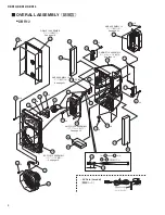
Page 67: ...8 DBR10 DBR12 DBR15 CABINET ASSEMBLY キャ ビネ ッ ト組立 DBR10 ...
Page 69: ...10 DBR10 DBR12 DBR15 CABINET ASSEMBLY キャ ビネ ッ ト組立 DBR12 ...
Page 71: ...12 DBR10 DBR12 DBR15 DBR15 CABINET ASSEMBLY キャ ビネ ッ ト組立 ...
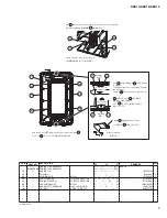
Page 80: ...21 DBR10 DBR12 DBR15 AMP ASSEMBLY アンプ組立 6 03 66 0 シールド AMP 組立 6HH SDJH 63 1 A ...
Page 83: ...24 DBR10 DBR12 DBR15 6 03 66 0 シールド AMP 組立 6 63 66 0 シールド DSP 組立 ...


