For Service Engineer
Service Information
SI1604009E-002= S20, S10, M20, M10 and D10 installation procedures
12/34
3.6 Install the machines temporarily
Load the machine onto a hand lifter and move it to the location where the customer designates
and unload the machine.
Step 1. Move the machine aligning with the reference position.
There is a case that marking on the floor is already completed by the customer side.
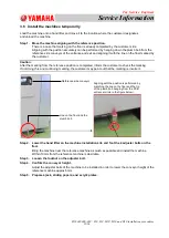
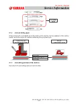
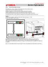
Aligning with the position accurately can be performed by hanging down the plumb bob from the
reference side conveyor of the entrance and exit and aligning it with the line on the floor marked by
the customer.
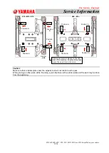
Caution:
After the marking from the reference position is completed, inform the customer to check the marking.
If not doing this and continuing marking, the customer may point out that the marking is incorrect.
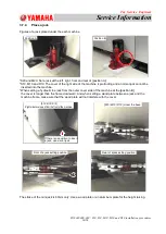
Step 2. Lower the hand lifter on the machine installation site and foot the 4 adjuster bolts on the
floor.
Bring the machine near the reference machine as much as possible and install the machine.
Within 10mm from the reference machine is desirable.
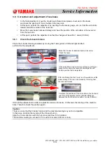
Step 3. Loosen the locknut on the adjuster bolt.
Step 4. Confirm the conveyor height.
Adjust the adjuster bolts of the machine to be installed in order to lower the conveyor height of the
reference machine approx.5mm.
Step 5. Prepare a jack, sliding papers, and acrylic plates.
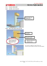
Reference side conveyor
Line on the floor and the
plumb bob
Aligning with the position is performed by
matching the line on the floor and the tip
of the plumb bob hanging from the PCB
entrance (circle in the figure below).

