background image

E-IDE (ATAPI) Connection Set Up

42

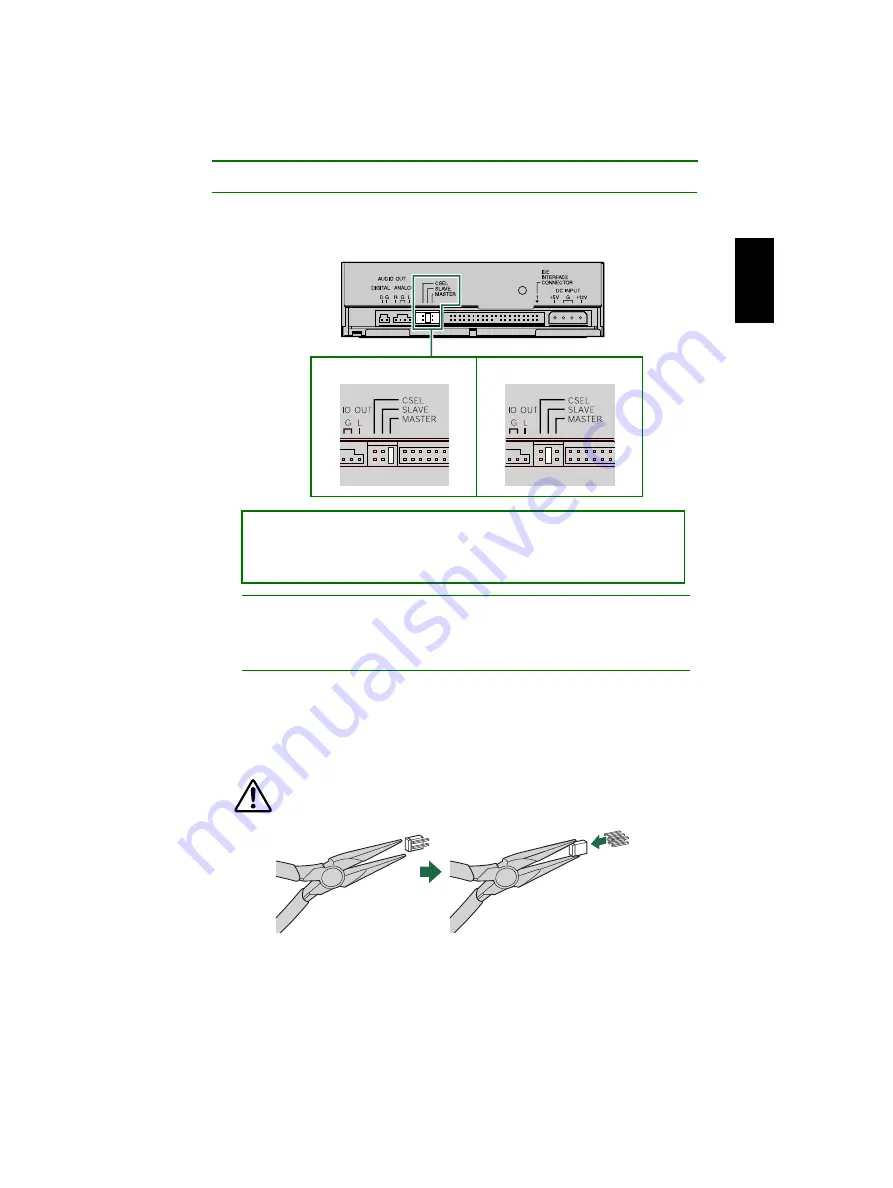
Setting the Jumper Switches

5

Set the CRW2200E as MASTER or SLAVE to meet your computer 
environment by plugging the included plastic shunt into the appropriate 
jumper switch on the rear panel of the CRW2200E.

Note

The plastic shunts actually contain metal for bridging the two pins of a jumper switch, 
creating an electrical connection between them when attached.  When removed, the jumper 
switch is set to “OFF.” Store unused plastic shunts in a safe place where they will not be lost.

About the CSEL jumper switch

If your computer supports the CSEL function, you can plug a plastic shunt into this jumper 
switch to have the computer automatically select MASTER or SLAVE for the CRW2200E
However, we recommend using the MASTER or SLAVE jumper switch because the CSEL 
function sometimes creates a conflict. Refer to the documentation that came with your 
computer to check whether the computer supports the CSEL function.

Use a pair of long-nosed pliers to attach or detach the plastic shunts 
accordingly. However, make sure that the computer is powered down 
when doing so.

The CRW2200E is shipped with the SLAVE setting.  Thus, you do not need to 
reset the factory setting if you plan to use the CRW2200E as SLAVE.  If you 
connect the drive solely to the secondary IDE cable or replace the drive with an 
existing master device, you need to reset the CRW2200E as MASTER.

Rear Panel

Master

Slave (factory setting)

Summary of Contents for CRW2200S Series

Page 1: ...i OWNER S MANUAL English ...

Page 2: ...s or foreign objects into the device Otherwise there is an increased risk of personal injury electrical shock damage to the device or fire Please take particular care if small children are present Do not expose the device to rain or use it near water or in damp or wet conditions Do not place containers on it that contain liquids which might spill into any openings Otherwise there is an increased r...

Page 3: ...he disc from the tray before transporting the device Otherwise written data may be destroyed When cleaning the device never use benzene paint thinners detergents or chemically coated wiping cloths Also do not place vinyl plastic or rubber objects on the device Otherwise the device may be damaged or its front panel may become discolored Use a soft dry cloth to wipe the device Do not rest your weigh...

Page 4: ...device always put it in its original box If the device is transported without adequate packing the internal components may be damaged and cause the device to malfunction Copyrights When writing to CD R RW make sure that you are not infringing any copyrights It is illegal to copy audio CDs for non personal use When backing up software please make sure that you are not infringing any software copyri...

Page 5: ...art 36 Connecting the CRW2200E 37 Operation 50 Loading a Disc 50 Ejecting a Disc 50 Ejecting a Disc in an Emergency 51 Troubleshooting 52 Appendix 57 Writing Modes 57 About firmware 59 LED Indicator Messages 60 CRW2200 Specifications 60 Index 64 2001 YAMAHA CORPORATION All Rights Reserved This document may not in whole or in part be copied photocopied reproduced translated transmitted or reduced t...

Page 6: ...I Connection SCSI Connection Set Up P 12 31 Attach the SCSI convertor to the CRW2200 drive In this manual the drive plus the convertor is called the CRW2200S Notes For a SCSI connection use the following items included SCSI convertor Screw Power cable The included SCSI convertor is for the CRW2200 drive only Do not use it with any other device YAMAHA and its suppliers do not guarantee operation if...

Page 7: ...se interference of the laser beam so that it projects accurately onto the disc Jitter value an important measure of recording quality has been improved 25 compared with Yamaha models not using this technology Running OPC Optimum Power Control Running OPC automatically adjusts the output of the laser according to the characteristics of the disc being used Running OPC provides greatly enhanced recor...

Page 8: ...n Yamaha s CRW2200 series CD R RW drives When a buffer underrun is about to occur a buffer underrun error is prevented by temporarily suspending the writing process Writing resumes when enough data has accumulated again in buffer memory Buffer Underrun Protection on the CRW2200 series is extremely accurate resulting in seamless recording between stop and continuation points Yamaha Buffer Underrun ...

Page 9: ...t came with it Operating System OS Windows 95 OSR2 or later Windows 98 Windows 98 Second Edition Windows Me Windows NT4 0 with Service Pack 3 or later Windows 2000 Professional CD Writing Software The CRW2200 drive requires CD writing software to write onto a CD R RW disc When you use the CD writing software make sure that it supports the CRW2200 drive Note For details about how to install and use...

Page 10: ...rite at 2X or 4X speed on the first type of disc and at 2X on the second type of disc These discs can be read played on a device e g CD ROM drive that supports CD RW High Speed CD RW discs 3 These discs allow writing rewriting at 4X to 10X speeds The CRW2200 drive can write rewrite these discs at 4X 8X or 10X speed These discs can be read played by a CD RW drive that bears the High Speed CD RW log...

Page 11: ...peed will vary in CLV writing In contrast the CAV Constant Angular Velocity method uses a constant disc rotation speed for all portions of the disc so that the data transfer rate will vary Because the CAV method has the advantage of largely increasing the data transfer rate with a minimum load to the drive s mechanism compared to CLV s rotation speed adjustment many current CD ROM drives use the C...

Page 12: ...ing rewriting is enabled with the CLV method When writing rewriting with packet writing you can also select the Full CAV method For more details refer to the documentation that came with your CD writing software Make sure that your CD writing software supports the Full CAV method The included CD writing software is supported For direct editing of a file on a CD RW disc the Full CAV method is recom...

Page 13: ...umber found at the top of the drive with the bar code You may need to refer to this number when requesting Customer Support services In the box below the following diagram write down the 10 character serial number consisting of 3 letters followed by 7 digits Serial Number Serial No Serial number 3 letters and 7 digits ...

Page 14: ...need to open or close the tray Remove the disc after the tray has opened P 50 Headphone jack You can connect stereo headphones to this stereo mini jack and listen to an audio CD loaded in the drive Headphone volume control Adjust this control to set a suitable volume level when listening to an audio CD using the headphone jack Slide the knob to the left to decrease the volume and to the right to i...

Page 15: ...9 34 DIGITAL AUDIO OUT connector If your sound card has a SPDIF digital audio input connector you can connect the DIGITAL AUDIO OUT connector of the unit to the SPDIF connector using a digital audio cable sold separately P 17 34 ANALOG AUDIO OUT connector Connect one end of the 4 pin audio cable to this connector and the other end to your computer s sound card or built in audio P 16 34 DC INPUT co...

Page 16: ...e 4 pin audio cable to this and the other end to your computer s sound card or built in audio P 16 44 Jumper switch Plug a plastic shunt into this jumper switch to select the connection either IDE master or slave The CRW2200 drive s factory setting is SLAVE P 42 IDE INTERFACE CONNECTOR Insert the connector of the IDE cable here P 43 DC INPUT connector Insert the power connector from your computer ...

Page 17: ... You may also need to temporarily remove the sound card to gain access to the CD audio connectors in which case a small screw retaining the sound card s face plate has to be removed Note Make sure your phillips screwdriver s head is the correct size for the screws you need to remove Long Nosed Pliers You will need these to insert or remove the plastic shunts when setting the jumper switches at the...

Page 18: ... P 20 5 Choosing the Connecting Method P 24 6 Installing the CRW2200S P 25 STEP 1 Configuring for the Operating System P 30 31 1 Check that the CRW2200S is recognized correctly P 30 2 Enabling the Sync data transfer P 31 STEP 2 Installing the CD Writing Software For details about how to install the software refer to the documentation that came with it STEP 3 Start Using the CRW2200S Use the drive ...

Page 19: ... Opening the Computer 1 1 1 1 Shut down your computer and unplug it from the AC outlet If you proceed without doing this you run the risk of receiving an electric shock and or short circuiting and damaging components including the CRW2200S 2 2 2 2 Remove all attached cables and peripheral devices and the outer casing of the computer If you need to remove screws in the process make sure you don t l...

Page 20: ...e computer s chassis or power supply unit to discharge any static electricity from your body Or wear an anti static grounding wrist strap You can permanently damage your equipment if you touch it with static electricity in your body Discharge any static charge ...

Page 21: ...dio cable When creating an audio CD if you use the SCSI flat cable to send the signal you do not need to connect an audio cable If you use the CRW2200S as a supplemental drive for the unit and the CD ROM drive or DVD ROM drive is already connected to the sound card YAMAHA recommends you playback audio CDs using the existing drive There are two methods of connecting the unit and the sound card an a...

Page 22: ...ital connection to connect the unit and the sound card With this connection you can Enjoy music using a digital audio amplifier Record music digitally with an MD player Connect the digital audio cable to the DIGITAL AUDIO OUT connector on the rear panel of the CRW2200 drive making sure of the connector s direction Note For the digital connection you need a digital audio cable with appropriate conn...

Page 23: ... when installing Otherwise it may cause damage 5 5 5 5 Attach the SCSI convertor included to the rear of the CRW2200 drive 6 6 6 6 Secure the SCSI convertor to the CRW2200 drive with the screw included Note Do not apply excessive force when tightening the screw The jumper switch for the IDE settings on the rear panel of the CRW2200 drive can be set to any of MASTER SLAVE CSEL This setting does not...

Page 24: ...ertor with the yellow wire to the left See the figure below Note These connectors are D shaped so you can only connect the power cables in the correct orientation Do not apply excessive force when making this connection You risk damaging the convertor if you make these connections upside down Power cable Bottom Top DC INPUT connector Bottom Top Yellow wire Smaller connector Bigger connector ...

Page 25: ... with a plastic shunt Shunts are already attached to the jumper switches in their default configurations Note The plastic shunts actually contain metal for bridging the two pins of a jumper switch creating an electrical connection between them when attached When removed the jumper switch is set to OFF Store unused shunts in a safe place where they will not be lost Use a pair of long nosed pliers t...

Page 26: ...number for each device on the chain must be unique Make sure the CRW2200S s SCSI ID number is not the same as that of any other device on the chain By factory default the CRW2200S is assigned ID number 3 but this can be changed ID SELECT PARITY TERMINATOR BLOCK SIZE 1 2 4 ID SELECT PARITY TERMINATOR BLOCK SIZE 1 2 4 ID SELECT PARITY TERMINATOR BLOCK SIZE 1 2 4 ID SELECT PARITY TERMINATOR BLOCK SIZ...

Page 27: ...inator switch should be set to ON if the CRW2200S is the last device on the internal SCSI chain If the CRW2200S is not the last device on the internal SCSI chain the shunt on the Terminator jumper switch should be removed ID SELECT PARITY TERMINATOR BLOCK SIZE ID SELECT PARITY TERMINATOR BLOCK SIZE 1 1 2 2 4 4 Parity ON Default Normally leave this setting alone Parity OFF The setting allows for th...

Page 28: ...shows the capacity of a sector that is the unit of data management of OS Note By factory default the Block Size jumper switch is set to OFF and should normally be left in this state ID SELECT PARITY TERMINATOR BLOCK SIZE ID SELECT PARITY TERMINATOR BLOCK SIZE 1 1 2 2 4 4 Termination ON Default Termination OFF Set to ON if CRW2200S is last device on SCSI chain Set to OFF if the CRW2200S is not the ...

Page 29: ...00S supplemental to the computer s existing CD ROM drive As a replacement drive If the casing of your computer does not have a spare 5 25 inch drive bay available such as with many desktop type computers you can replace the computer s existing CD ROM drive with the CRW2200S Note You cannot replace the computer s existing CD ROM drive with the CRW2200S using the existing cable if the drive is a IDE...

Page 30: ...your computer In the illustration below the devices show are all IDE type The procedure for SCSI type installation is the same Notes Care should be taken not to damage cables connected to the rear of the CD ROM drive The Audio connecting cable is equipped with a locking mechanism to secure it in place To release the lock lift up the connector and gently pull it out Do not apply excessive force to ...

Page 31: ...old the drive in place Notes Do not apply excessive force when sliding the drive backwards into the drive bay slot Leave enough room behind the drive to connect the power SCSI and audio cables 12 12 12 12 Connect one end of the 50 pin SCSI flat cable to the computer s SCSI card Align the colored line of the cable with Pin 1 of the card s SCSI connector Next connect a free 50 pin connector on the S...

Page 32: ...r to the documentation that came with your sound card for more details and make sure that your audio cable is connected correctly Connecting the digital audio cable Connect the digital audio cable to the SPDIF input connector digital audio of the sound card making sure of check of the connector s direction Note For the digital connection you need a digital audio cable with appropriate connectors a...

Page 33: ... one 4 pin power cable available Any one may be used These connectors are D shaped so you can only connect the power cables in the correct orientation Do not apply excessive force when making this connection 15 15 15 15 Tighten the four fastening screws on the side of the unit securely using a phillips screwdriver 4 pin power cable Bottom Top Bottom Top Power cable ...

Page 34: ... devices of the computer and any screws that were removed 17 17 17 17 Reconnect the computer to the AC outlet and turn it on When you turn on the computer make sure the LED on the panel of the CRW2200S blinks in green which indicates that it is reading disc information P 60 Cover Front panel ...

Page 35: ...own below if it has been properly installed This is a screen shown in the Windows Me environment For Windows NT You can verify by opening Control Panel double clicking on SCSI Adapter and clicking on the Devices tab For Windows 2000 Professional You can verify by opening Control Panel double clicking on System selecting the Hardware tab and clicking on the Device Manager button in System Propertie...

Page 36: ...he maximum possible data transfer rate can be achieved This is a screen shown in the Windows Me environment Notes For details refer to the documentation that came with your SCSI card When using Windows NT 2000 Professional Sync data transfer will automatically be selected if the SCSI card supports this feature You will not need to change this setting Installing the CD Writing Software 20 20 20 20 ...

Page 37: ... came with your computer Do not touch the connector pins or the circuit board Otherwise it may cause a malfunction with the SCSI convertor Please follow the instructions below Do not use excessive force when installing Otherwise it may cause damage 1 1 1 1 Shut down your computer and unplug it from the AC outlet P 14 step 1 1 1 1 2 2 2 2 Remove all attached cables and peripheral devices and the ou...

Page 38: ... the CRW2200S and remove it from the computer If the audio cable is connected to the CRW2200S disconnect the sound card s side connector only 5 5 5 5 Remove the screw securing the SCSI convertor to the CRW2200 drive Audio cable 50 pin SCSI flat cable 4 pin power cable Screw ...

Page 39: ...e smaller connector connected to the SCSI convertor is locked with its hook Lift up the connector to unlock the hook then pull it out See the figure below If the audio cable is connected disconnect it after removing the convertor An analog audio cable connection is shown in the figure below SCSI convertor Power cable Analog audio cable Smaller connector Bigger connector ...

Page 40: ...ter and when mounting the drive You may also need to temporarily remove the sound card to gain access to the CD audio connectors in which case a small screw retaining the sound card s face plate has to be removed Note Make sure your phillips screwdriver s head is the correct size for the screws you need to remove Long Nosed Pliers You will need these to insert or remove the plastic shunts when set...

Page 41: ...nfiguring for the Operating System P 47 48 1 Check that the CRW2200E is recognized correctly P 47 2 DMA Settings P 48 STEP 3 Installing the CD Writing Software For details about how to install the software refer to the documentation that came with it STEP 4 Start Using the CRW2200E Use the drive to create audio CDs to back up data on your hard disk or for whatever purpose suits your needs STEP 5 D...

Page 42: ...low the procedures in the documentation that came with your computer Opening the Computer 1 Shut down your computer and unplug it from the AC outlet P 14 step 1 1 1 1 2 2 2 2 Remove all attached cables and peripheral devices and the outer casing of the computer If you need to remove screws in the process make sure you don t lose them Remove the cover and front panel of the computer P 14 step 2 2 2...

Page 43: ...y tower type designs you can install the CRW2200E supplemental to the computer s existing CD ROM drive As a replacement drive If the casing of your computer does not have a spare 5 25 inch drive bay available such as with many desktop type designs you can replace the computer s existing CD ROM drive with the CRW2200E Note You cannot replace the computer s existing CD ROM drive with the CRW2200E us...

Page 44: ...es When you are using the IDE device as a master connect the device to the connector of the leading edge of the IDE cable or you are using the device as a slave connect the device to the connector of the middle of the IDE cable When you connect two IDE devices to one IDE cable assign each as MASTER or SLAVE respectively The CRW2200E is shipped with the SLAVE setting Typical IDE type hardware insta...

Page 45: ... unit To make the best use of the performance of the CRW2200E Yamaha recommends you connect it as a sole secondary master Note The CRW2200E is shipped with the SLAVE setting Reset to MASTER if you connect the drive solely to the secondary IDE cable CRW2200E slave CD ROM drive etc master Hard disk master Hard disk slave IDE cable primary IDE cable secondary CRW2200E master Hard disk master IDE cabl...

Page 46: ...able When the operating system starts with the SCSI hard drive a primary IDE connector may have no IDE devices In such a case Yamaha recommends you connect the CRW2200E as a primary master When you connect the removed IDE type hardware to the other connector of the cable some cables may have only one connector In such a case use the cable with two connectors ...

Page 47: ...unt into this jumper switch to have the computer automatically select MASTER or SLAVE for the CRW2200E However we recommend using the MASTER or SLAVE jumper switch because the CSEL function sometimes creates a conflict Refer to the documentation that came with your computer to check whether the computer supports the CSEL function Use a pair of long nosed pliers to attach or detach the plastic shun...

Page 48: ...he colored line on the cable corresponds to pin 1 on the right end of the connector The pin 1 of the IDE connector is labeled on the motherboard or refer to the documentation that came with your computer Notes The included IDE cable supports the UltraDMA 33 mode and does not support the UltraDMA 66 mode and the UltraDMA 100 mode Please note that the IDE devices connected to the included IDE cable ...

Page 49: ...ive is already connected to the sound card YAMAHA recommends you playback audio CDs using the existing drive There are two methods of connecting the unit and the sound card an analog connection and a digital connection Connecting the analog audio cable Connect one end the end which has one connector of the included audio cable to the ANALOG AUDIO OUT connector on the rear panel of the CRW2200E Mak...

Page 50: ...signals recorded on CDs to the sound card without any distortion Examples of the digital connection To output digital audio signals to external devices you must use the digital connection to connect the unit and the sound card With this connection you can Enjoy music using a digital audio amplifier Record music digitally with an MD player Use the digital audio cable to connect the DIGITAL AUDIO OU...

Page 51: ...ction 11 11 11 11 Tighten the four fastening screws on the side of the unit securely using a phillips screwdriver P 28 step 15 15 15 15 12 12 12 12 Attach the outer casing and all cables and peripheral devices of the computer and any screws that were removed P 29 step 16 16 16 16 13 13 13 13 Reconnect the computer to the AC outlet and turn it on P 29 step 17 17 17 17 When you turn on the computer ...

Page 52: ...elow This is a screen shown in the Windows Me environment For Windows NT You can verify by opening Control Panel double clicking on SCSI Adapter and clicking on the Devices tab For Windows 2000 Professional You can verify by opening Control Panel double clicking on System selecting the Hardware tab and clicking on the Device Manager button in System Properties Notes For details about how to use th...

Page 53: ...ecome unstable If this occurs uncheck DMA This is a screen shown in the Windows Me environment Notes Windows NT does not have the DMA setting Nor do you need to set the Sync data transfer parameter since it will not appear For Windows 2000 Professional To set the DMA log on as an Administrator Open the Device Manager window and double click on IDE ATA ATAPI controllers then double click on the IDE...

Page 54: ...n that came with it About DMA DMA Direct Memory Access is a method that transfers data between various peripheral devices e g a hard drive CD R RW drive etc and the computer s memory without using the CPU By checking the DMA check box the transmission speed of data will become high speed Furthermore by decreasing the CPU load the processing speed of the computer systems is increased ...

Page 55: ... tray by pressing the Eject button again You can also gently push it closed Load or unload the disc after the tray has fully opened Do not push or pull the tray using excessive force Doing so can damage the drive or the disc 1 1 1 1 Open the tray by pressing the Eject button on the CRW2200 drive s front panel 2 2 2 2 Remove the disc from the tray 3 3 3 3 Close the disc tray by pressing the Eject b...

Page 56: ... spring loaded mechanism or power outage it can be opened manually You should attempt to eject a disc manually only as a last resort Malfunctions may occur if you do this too frequently 1 1 1 1 Shut down the computer 2 2 2 2 Find a pin like tool with a diameter of 2mm or less to fit through the Manual Eject hole on the drive s front panel Note A straightened large paper clip is ideal for this purp...

Page 57: ...ct direction P 37 46 The computer does not start up Is the SCSI card installed correctly Please read the instructions that came with your SCSI card for details The CRW2200S is not recognized In the case of SCSI connection Is the 4 pin power cable from the computer s power supply attached correctly and does the drive turn on Also is the SCSI cable connected correctly If the system has started up no...

Page 58: ...FF P 22 Is the termination on the SCSI card set such that internal SCSI devices can be connected Please read the instructions that came with your SCSI card for details Check other SCSI devices to eliminate the possibility of troubles If you use more than one SCSI device simultaneously it may cause a trouble on your device drivers or data transfer speed for some reason Disconnect other SCSI devices...

Page 59: ... To write to CD R RW discs your CD writing software must support the CRW2200E To find out if it does contact the manufacturer of your CD writing software The disc tray does not open Is the CRW2200 drive turned on The LED on the front panel of the CRW2200 drive lights up Some CD writing software will lock the disc tray once loaded In this case use the eject command from within the software Refer al...

Page 60: ... shown below When you are using the Windows Media Player 7 0 with Windows Me above symptom is known to exist because the initial setting default to ON for the Digital playback Note The following procedures are described for a SCSI connection For the connection of the E IDE ATAPI models please give the CRW2200E name to the CRW2200S 1 The Properties setting of the CRW2200S Open the YAMAHA CRW2200S P...

Page 61: ...e writing and to avoid causing Buffer Underrun try the following Lower the writing speed setting Create an image file of the CD on the computer s hard disk Optimize the hard drive Defragment the drive When writing close other applications including screen savers etc Turn hard disk power management off Select Sync data transfer for the setting of transfer mode of the SCSI devices such as a hard dri...

Page 62: ... added later if there is enough space left on the disc This is why Track at Once mode is sometimes referred to as Multisession Note Only the first session of a multisession disc can be played back on a conventional audio CD player Single session discs can be played back completely Writing Modes Data Example General CD ROM Session 1 Track 1 Any remaining space cannot be used 0 Lead in Lead out Audi...

Page 63: ...ental backups of data You will need to use software that specifically supports packet writing such as Adaptec s Direct CD Notes on Packet Writing Discs must be formatted before they can be used for packet writing With CD RW erased data can be overwritten until the disc is completely full When using packet writing on a CD RW disc the actual data capacity is 100MB less than that stated on the cover ...

Page 64: ...ularly Determining the firmware version of the CRW2200 drive in Windows 95 98 98 Second Edition Me Go to Control Panel System Device Manager tab double click on CDROM then double click on YAMAHA CRW2200S Note The following procedures are described for a SCSI connection For the connection of the E IDE ATAPI models please give the CRW2200E name to the CRW2200S For Windows NT You can verify by openin...

Page 65: ...c information TOC Blinking constant Green Initial access in writing Blinking constant Orange Writing test mode Blinking constant Orange Writing Blinking fast constant Orange Reading Flashing inconstant Green Playing Blinking fast constant Green Power saving combined with the computer s power saving Out Failure Flashing inconstant Orange CRW2200 Specifications Write Read Play CD DA 4 CD TEXT CD ROM...

Page 66: ...ting speeds CD RW 2X writing rewriting Rewritable discs specified in Orange Book Part III Volume 1 Version 1 0 2X or 4X writing rewriting Rewritable discs specified in Orange Book Part III Volume 1 Version 2 0 4X 8X 10X CLV 4X 10X Full CAV writing rewriting Rewritable discs specified in Orange Book Part III Volume 2 Version 1 0 Data Capacity 700MB 79 min 650MB 74 min 550MB 63 min Data Transfer Rat...

Page 67: ...Out Analog audio output Frequency range 20 20 000 Hz Output level 700mVrms Digital audio output Format SPDIF Output level TTL Power Consumption CRW2200 drive 11W when writing or reading 4W standby SCSI convertor 1W Power Supply 5V DC 5 12V DC 10 Operating Environment Temperature 5 40ºC Humidity 25 80 RH no condensation Dimension Width 148 0 mm Height 42 6 mm Depth 198 1 mm CRW2200 drive only 216 7...

Page 68: ...ubpart B Class B Computing Device Canada Safety Electrical CSA C22 2 No 60950 Information Technology Equipment EMC Emission ICES 003 Class B Computing Device EU Safety Electrical EN60950 Information Technology Equipment Laser EN60825 Class 1 Laser Product EMC Immunity EN55024 Residential Commercial and Light Industrial Areas Emission EN55022 Class B Equipment Australia New Zealand EMC Emission AS ...

Page 69: ...T connector 10 11 19 46 Device Manager 30 47 59 Digital audio cable 17 27 45 DIGITAL AUDIO OUT connector 10 11 17 45 Disc tray 9 50 Disc at Once DAO 57 DMA 48 49 E Eject button 9 50 Ejecting a Disc 50 Ejecting a Disc in an Emergency 51 Extraction of digital audio data 2 F Firmware 59 Front cover 25 Front Panel 9 Full CAV 7 H Headphone jack 9 Headphone volume control 9 High Speed CD RW discs 5 I ID...

Page 70: ... R Rear Panel 10 11 Removing the SCSI convertor 32 Running OPC 2 S SafeBurn 2 Screw 18 33 SCSI card 4 SCSI convertor 1 10 18 34 SCSI driver 53 SCSI ID number 21 59 SCSI INTERFACE connector 10 26 Secondary 39 Serial Number 8 Session 57 Session at Once SAO 58 Single session 57 SLAVE 39 42 Sound card 27 44 45 SPDIF 27 45 Sync data transfer 31 T Termination 22 Track 57 Track at Once TAO 57 V Video CD ...

Reviews: