


CL3/CL1
170
■
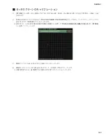
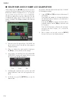
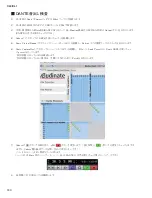
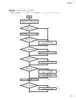
FADER CALIBRATION
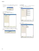
1)
While holding down the
[STORE]
key, turn on the power
switch, and the [Special Mode Screen] will appear, where
INITIALIZE, TRIM, CALIBRATION, etc. are executed.
2) Among MODE SELECT buttons, touch [FADER
CALIBRATION], and the fader calibration window will
appear.
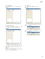
3) According to instructions on the screen and using the
[SEL]
key, select the fader for which CALIBRATION
will be executed. Select all the faders.
* It is possible to select only those faders which are subject
to calibration.
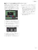
4)
Touch the START button in the screen. As a con
fi
rmation
screen will appear, touch the
[OK]
button to start
CALIBRATION.
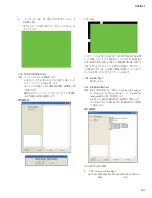
5) As “MOVE ALL SELECTED FADERS TO -
∞
dB and
Press
[NEXT]
Button” appears on the screen, apply all
the selected faders to the bottom and execute NEXT.
6) As “MOVE ALL SELECTED FADERS TO -20 dB and
Press
[NEXT]
Button” appears on the screen, align all the
selected faders to the -20 index and execute NEXT.
7) As “MOVE ALL SELECTED FADERS TO 0 dB and
Press
[NEXT]
Button” appears on the screen, align all the
selected faders to the 0 index and execute NEXT.
8) As “MOVE ALL SELECTED FADERS TO +10 dB and
Press
[NEXT]
Button” appears on the screen, apply all
the selected faders to the top and execute NEXT.
9) As “Calibrating the Faders…” appears on the screen and
the motor driven calibration is started, do not touch the
faders until it is completed.
10) When the motor driven calibration is over, the automatic
correction will start. While every 8 faders are driven
together, correction is made so that the movement time
becomes the same as much as possible. Do not touch
faders during this procedure.
11) When all the procedure is over, the
[APPLY]
button
appears on the screen. Check to make sure that SEL-LED,
CUE-LED and ON-LED at the top of each fader are all
turned off and press the
[APPLY]
button.
Even one LED is lit in Step 11) above, take following measures.
• When SEL-LED is lit
It is possible that positioning at any of 4 places in steps 5) to 8)
has failed.
As the
[RESTART]
button and
[APPLY]
button appear on the
screen, execute
[RESTART]
as necessary and do the procedure
again from Step 4.
• When CUE-LED is lit
In Step 9) above, full movement is not obtained at he speci
fi
ed
maximum voltage.
As the
[APPLY]
button appears on the screen, press it once
and slide the subject fader by hand about 10 times and again do
the procedure from Step 3).
• When CUE-LED and ON-LED are lit
Oscillation and vibration have occurred during operation of
Step 9) above.
Replace the subject fader.
Summary of Contents for CL3
Page 7: ...7 CL3 CL1 DIMENSIONS CL3 CL1 648 15 201 130 299 667 839 15 201 130 299 667 Unit mm...
Page 95: ...95 CL3 CL1 CPU Circuit Board Pattern side to DSP CN101 2NA WY67750 1...
Page 101: ...101 CL3 CL1 DNTU Circuit Board Pattern side Scale 80 100 2NA WZ20390 5...
Page 102: ...CL3 CL1 102 2NA WY63530 FX Circuit Board WR 63 1 Component side Scale 95 100...
Page 103: ...103 CL3 CL1 2NA WY63530 FX Circuit Board Pattern side Scale 95 100...
Page 105: ...105 CL3 CL1 HAAD Circuit Board Pattern side Scale 90 100 2NA WY64340 2...
Page 107: ...107 CL3 CL1 2NA WY63490 Component side JK Circuit Board WR 63 1...
Page 109: ...109 CL3 CL1 Component side TBPHN Circuit Board WR 06 1 WR 63 1 2NA WY64360 1...
Page 110: ...CL3 CL1 110 Component side PN8 Circuit Board to FD8 CN902 or FD8CN CN902 2NA WY53120 2...
Page 118: ...CL3 CL1 118 Component side PNENL Circuit Board to PN8 CN001 2NA WY53130 1...
Page 160: ...CL3 CL1 160 1 18 LCD Test LCD LCD 1 3 2 9 5 OK NG 1 2 H 3 O X O 4 BOX 5x4...
Page 382: ...7 MBCL CIRCUIT BOARDS A A A A 2NA WY53200 1 MB Circuit Board Component side...
Page 383: ...MBCL 8 MB Circuit Board DSUB PH CONNECTOR ASSEMBLY B B B B 2NA WY53200 1 Pattern side...


