CDC-585/CDC-506/CDC-685/CDC-906
CDC-585/CDC-506
CDC-685/CDC-906
■
MAIN P.C.B. CHECK
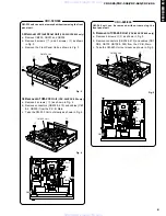
Preparation before MAIN P.C.B. Check
a. Remove the Top Cover.
b. Remove the Tray Ass'y
c. Remove 3 screws (
q
) on the Panel as shown in
Fig. 1.
d. Remove 2 screws (
w
) and 1 plastic rivet on the
Main P.C.B. as shown in Fig. 2.
e. Spread a cloth over the Main Chassis as shown in
Fig. 2.
f. Put the Main P.C.B. on end as shown in Fig. 2.
g. Connect the ground point of Main P.C.B. (2) to rear
panel by using wire as shown in Fig. 2.
h. Remove 7 screws (
e
) as shown in Fig. 3.
i. Remove 5 screws (
r
) and 1 screw (
t
) as shown
in Fig. 4.
j. Remove the front panel from the Main Chassis.
Plastic Rivet
q
w
w
Rear Panel
P.C.B. Main
e
r
Front Panel
r
r
t
r
Front Panel
Top View
Fig. 1
Fig. 3
Fig. 2
Fig. 4
10
CAUTION :
The ground point must be connected to
rear panel to keep the circuit in normal
operation when Main P.C.B. is removed
from main chassis.
Cable
Cloth
P.C.B. Main
Rear Panel
Solder the end of the wire to the ground point
of Main P. C. B. (2). (refer to P.31/P.33 F-2)
www. xiaoyu163. com
QQ 376315150
9
9
2
8
9
4
2
9
8
TEL 13942296513
9
9
2
8
9
4
2
9
8
0
5
1
5
1
3
6
7
3
Q
Q
TEL 13942296513 QQ 376315150 892498299
TEL 13942296513 QQ 376315150 892498299


