


2
Chapter 1 : Introduction
2
Chapter 1 : Introduction
2
Chapter 1 : Introduction
Unpacking
The CBX-D3 package should contain the following items.
Retain the packing materials for future use.
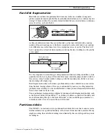
Installation
The CBX-D3 comes equipped with mounting brackets at both sides, allowing easy
installation on any standard 19" electronic equipment rack. (The unit requires 1U of rack
space.)
If you need to remove the mounting brackets, simply remove the three screws holding each
bracket in place. Be sure to reuse the same screws when reattaching the brackets; use of a
different screw size can cause internal damage.
Trademarks
Macintosh is a registered trademark of Apple Computer, Inc.
All other trademarks are the property of their respective holders.
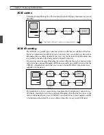
Powering up a CBX-D3 System
Some computers are particular about the order in which devices are powered up. It is
generally best to switch on all peripheral SCSI devices before turning on the computer.
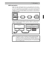
Downloading the System Software
Immediately following power-on, the CBX-D3 must download system data from the
computer. The 48kHz LED blinks to indicate that download is not yet completed.
CBX-D3 applications perform the download automatically. If you are working with a
CBX-D5 application, you will need to run the download yourself using a “System
Downloader” program, available on request from your Yamaha CBX-D3 dealer.
1
CBX-D3
Serial No:
1
PA-5B AC Adaptor (or recommended equivalent)
2
1U rack mounting brackets (attached to the CBX-D3)
1
Owner’s Manual
1
User Registration Card
NOTE:
To avoid system crash and data loss, NEVER switch off or disconnect any of
the SCSI devices while the CBX-D3 system is running.
NOTE:
Consult your Yamaha CBX-D3 dealer for information about the latest
CBX-D3 applications.
POWER
S
ON/
T
OFF
PHONES
VOLUME
DIGITAL RECORDING PROCESSOR CBX-D3
SAMPLING FREQ
1 INPUT LEVEL 2
SCSI
MIDI
48
44.1
32
22.05
OUTPUT MONITOR
INPUT LEVEL
1
2
3
4
CLIP
-6
-24
1 2
1 MIC 2
3 screws
3 screws