Yamaha CBX-D3 Owner'S Manual Download Page 23

INPUT LEVEL indicators17

INPUT LEVEL indicators17

INPUT LEVEL indicators

17

INPUT LEVEL indicators

Unlike analog tape recorders, digital audio recorders are very unforgiving when it comes 
to excessive signal levels. Digital audio signal clipping normally produces unpleasant 
distortion, pops, and clicks that can be impossible to remove without the use of highly 
sophisticated editing equipment. So great care must be taken when setting the recording 
level.

With a digital audio recorder such as the CBX-D3, noise and hiss produced by setting the 
recording level too low are not a problem. But setting the level too low reduces the 
effective dynamic range of the recording. In general, you want to use as much of the 96dB

*


dynamic range as possible.

Basically, the recording level should set so that the loudest signals light the –24 and –6 
LEDs, but never the CLIP LEDs. When recording with microphones, where sudden signal 
surges are possible, it may be worth having a “dry run” before you hit the record button.
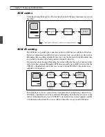
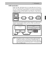
8  Playback 

Sampling Frequency for Playback

Although digital audio devices generally use the same sampling frequency for both 
recording and playback, the CBX-D3 includes a sampling frequency converter (SFC) that 
allows playback at a different frequency from that used to record. This feature makes it 
possible to replay multiple files at the same frequency, regardless of the frequencies 
originally used for recording. Specifically, the CBX-D3 can replay sound files using any 
of four sampling frequencies (44.1, 48, 32, or 22.05kHz). The frequency is selected 
through the controlling software, usually so as to match the sampling frequency of the 
device (such as digital mixer or DAT, MD, or DCC recorder) to which digital sound is 
being sent. The SAMPLING FREQ indicator on the CBX-D3 indicates the selected 
frequency.

The sampling frequency used for recording determines the maximum sound quality 
obtainable from the file; use of higher frequencies at time of playback will not improve the 
quality. If you recorded a file at a 44.1kHz sampling frequency, it will not sound any 
different when replayed at 48kHz. But you should also note that a sound file recorded at 
48kHz will generally suffer no noticeable quality loss when replayed at 44.1kHz.

OUTPUT MONITOR indicators

The four OUTPUT MONITOR indicators show the current output level of each channel. 
Each indicator consists of a single LED which gets gradually brighter as the channel’s 
output level increases. Output levels can be controlled by software.

* 96dB is the dynamic range available from a 16-bit digital system (6dB per bit).

Summary of Contents for CBX-D3

Page 1: ......

Page 2: ...sting service ENVIRONMENTAL ISSUES Yamaha strives to produce products that are both user safe and environmentally friendly We sincerely believe that our products and the production methods used to pro...

Page 3: ...cate either this product or the device that is being affected by the interference Utilize power outlets that are on different branch circuit breaker of fuse circuits or install AC line filter s In the...

Page 4: ...CBX D3 Mode d emploi Bedienungsanleitung Owner s Manual English Fran ais Deutsch English Fran ais Deutsch...

Page 5: ...marking indicating the type of receptacle to use To reduce the risk of electric shock do not remove the cover of the CBX D3 To reduce the risk of fire or electric shock do not expose the CBX D3 to rai...

Page 6: ...nt panel 6 Rear panel 8 5 Connecting Hard Disk Drives 10 What type of hard disk 10 Hard disk size 10 Choosing a hard disk 11 SCSI 11 SCSI cables 12 SCSI ID setting 12 SCSI termination 13 6 Working wit...

Page 7: ...level automatically switches to accommodate line or microphone input One CD DAT digital output Available recording time is limited only by hard disk capacity You can increase the recording time by in...

Page 8: ...itch on all peripheral SCSI devices before turning on the computer Downloading the System Software Immediately following power on the CBX D3 must download system data from the computer The 48kHz LED b...

Page 9: ...devices For details about how to connect hard disk drives refer to page 10 Sound files Just like other types of computer data digital audio data is stored in files sound files When recording starts a...

Page 10: ...and hard disk by SCSI It is also connected to the computer by MIDI cables The SCSI connection supplies control data from the computer and transfers audio data to or from the hard disk for recording o...

Page 11: ...MIDI IN SCSI Dedicated cable COMPUTER CBX D3 LINE IN X 4 ANALOG OUT X 4 LINE IN SCSI SCSI TERMINATOR CBX D3 applications automatically load system software to the CBX D3 at time of power on CBX D5 app...

Page 12: ...e headphone volume 4 SCSI indicator Red green LED indicator showing the current SCSI status GREEN indicates that the CBX D3 is reading from disk sending or receiving commands over the SCSI or download...

Page 13: ...ected to the analog inputs Note that the input level automatically changes to accommodate microphone or line input 0 MIC 1 2 Two 1 4 inch jacks for direct input of microphone analog audio signals Thes...

Page 14: ...are connected to both MIC andANALOG IN only the MIC nominal 60dBm signals will be received 4 ANALOG OUT 1 4 Four 1 4 inch phone jacks that output audio data in analog form These are unbalanced output...

Page 15: ...for multiple D A and A D conversions 8 SCSI ID selector A thumbwheel switch used to set the SCSI ID for the CBX D3 See SCSI ID setting page 12 for more information 9 SCSI connectors Two 50 pin Ampheno...

Page 16: ...quencies generate much more digital data and therefore require much more space For details about frequency selection refer to Sampling Frequency on page 16 Although it is doubtful that you will ever b...

Page 17: ...ontinue the SCSI daisy chain Are the SCSI connectors 25 pin D SUB or 50 pin Amphenol Macintosh computers are fitted with a 25 pin D SUB connector while most other SCSI devices use a 50 pin Amphenol co...

Page 18: ...bly crash so make sure that each device has a unique ID number SCSI devices usually have a DIP switch or like the CBX D3 a thumbwheel switch that you can use to set the ID Refer to the instructions su...

Page 19: ...d at the end of the daisy chain The CBX D3 and many other devices utilize a detachable in line terminator as illustrated below NOTE If the SCSI daisy chain is not terminated correctly numerous problem...

Page 20: ...es File management and backup Once you have stored sound files to disk you can copy delete or size check them using the same commands that you use for your other computer files You can also back them...

Page 21: ...th the incoming data In the worst case the recording will simply stop Disk fragmentation does not become a problem until you have deleted one or more files from the disk leaving islands of free space...

Page 22: ...e 48kHz 22 05kHz At this frequency an audio bandwidth of about 10kHz is available This frequency is widely used in multimedia applications It might not seem very useful for your audio applications but...

Page 23: ...ncy converter SFC that allows playback at a different frequency from that used to record This feature makes it possible to replay multiple files at the same frequency regardless of the frequencies ori...

Page 24: ...he SCSI bus is terminated correctly Make sure that all connected SCSI devices are powered up Use standard SCSI cables only Try another SCSI cable have your dealer check the cable Change the order of d...

Page 25: ...PLING FREQ setting is the same on the CBX D3 and the controlling software If after starting up the controlling software you change some CBX D3 settings via MIDI or another program the controlling soft...

Page 26: ...ment LED 2 channels CH1 CLIP red 6 orange 24 green CH2 CLIP red 6 orange 24 green OUTPUT MONITOR 1 point variable brightness LED 4 channels SCSI Status 1 green red LED MIDI Message 1 green LED Control...

Page 27: ......

Page 28: ......

Page 29: ......

Reviews: