


8
Chapter 4 : Controls & Connections
8
Chapter 4 : Controls & Connections
8
Chapter 4 : Controls & Connections
Rear panel
1
DC IN connector
Power connector. Connect one end of the supplied power-adaptor cord to this connector,
then insert the plug end of the cord into an appropriate AC receptacle.
2
Cable clip
Wrap the adaptor cord around this clip to help prevent accidental disconnection.
3
ANALOG IN 1&2
Two 1/4-inch phone jacks for direct input of analog audio signals. These are unbalanced
inputs with nominal input levels of –20dBm, and can be connected to the outputs of a
mixer, synthesizer, drum machine, or other such device.
Note that connecting a cable to the MIC jack on the front panel automatically disables the
corresponding ANALOG IN jack. If cables are connected to both MIC and ANALOG IN,
only the MIC (nominal –60dBm) signals will be received.
4
ANALOG OUT 1~4
Four 1/4-inch phone jacks that output audio data in analog form. These are unbalanced
output jacks with a nominal output level of –20dBm. You can connect these to a mixer,
amplifier, tape recorder, or DAT recorder.
If you connect a line to OUT1 only, the OUT1 jack will output audio signals for all four
channels. If you connect to OUT1 and OUT2 only, then OUT1 will output channels 1 and
3, while OUT2 will output channels 2 and 4.
NOTE:
Always set the INPUT LEVEL to minimum before inserting or removing a
microphone or line input.
NOTE:
For your convenience, the top panel includes illustrations and names of all terminals located on the
rear panel. This may help you locate cables and connectors without having to look behind the device.
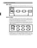
SCSI
SCSI ID
DIGITAL
OUT
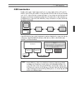
MIDI
IN
OUT
OUT 1
OUT 2
OUT 4
IN 1
IN 2
OUT 3
DC IN
ANALOG IN/OUT
2
3
4
9
1
5
6
7
8
5