
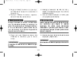


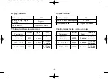


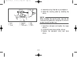


1. Float
2. Pin
3. Needle valve
4. Float arm
5. Main jet
1. Flotteur
2. Goupille
3. Pointeau
4. Bras du flotteur
5. Gicleur principal
1. Flotador
2. Pasador
3. Válvula de aguja
4. Brazo del flotador 5. Surtidor principal
8-47
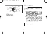
8. Remove the float chamber by removing the
screws.
9. Remove the float by removing the pin.
10. Remove the needle valve by unhooking it
from the float arm.
11. Change the main jet and the jet needle clip
position. (See page 8-41.)
NOTE:
An optional main jet can be obtained at a
Yamaha dealer.
Assembling the carburetor
1. Install the needle valve by hooking it onto
the float arm.
2. Install the float by inserting the pin into the
holder.
3. Install the float chamber by installing the
screws.
4. Connect the throttle cable onto the throttle
valve by installing the holder and the
screws.
1
2
2
2
5
3
4
1
2
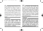
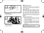
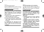
1. Float chamber
2. Screw
1. Cuve à flotteur
2. Vis (
×
4)
1. Cuba
2. Tornillo (
×
4)
1. Float chamber
2. Screw (
×
4)
1. Cuve à flotteur
2. Vis (
×
4)
1. Cuba
2. Tornillo (
×
4)
5VM-9-61-05 3/14/03 10:48 PM Page 48
Summary of Contents for BLASTER YFS200S
Page 2: ...5VM 9 61 01 3 14 03 9 34 PM Page 1 ...
Page 16: ...5VM 9 61 01 3 14 03 9 34 PM Page 15 ...
Page 28: ...1 4 5VM 9 61 01 3 14 03 9 34 PM Page 27 ...
Page 32: ...1 8 5VM 9 61 01 3 14 03 9 34 PM Page 31 ...
Page 36: ...1 12 5VM 9 61 01 3 14 03 9 34 PM Page 35 ...
Page 72: ...4 8 5VM 9 61 02 3 14 03 9 35 PM Page 9 ...
Page 167: ...7 1 Riding Your ATV 5VM 9 61 04 3 14 03 9 37 PM Page 2 ...
Page 168: ...7 2 Conduite Conducción du del VIT ATV 7 5VM 9 61 04 3 14 03 9 37 PM Page 3 ...
Page 264: ...8 16 5VM 9 61 05 3 14 03 10 48 PM Page 17 ...
Page 356: ...8 108 5VM 9 61 06 3 14 03 9 40 PM Page 1 ...
Page 382: ...10 16 5VM 9 61 06 3 14 03 9 40 PM Page 27 ...