n
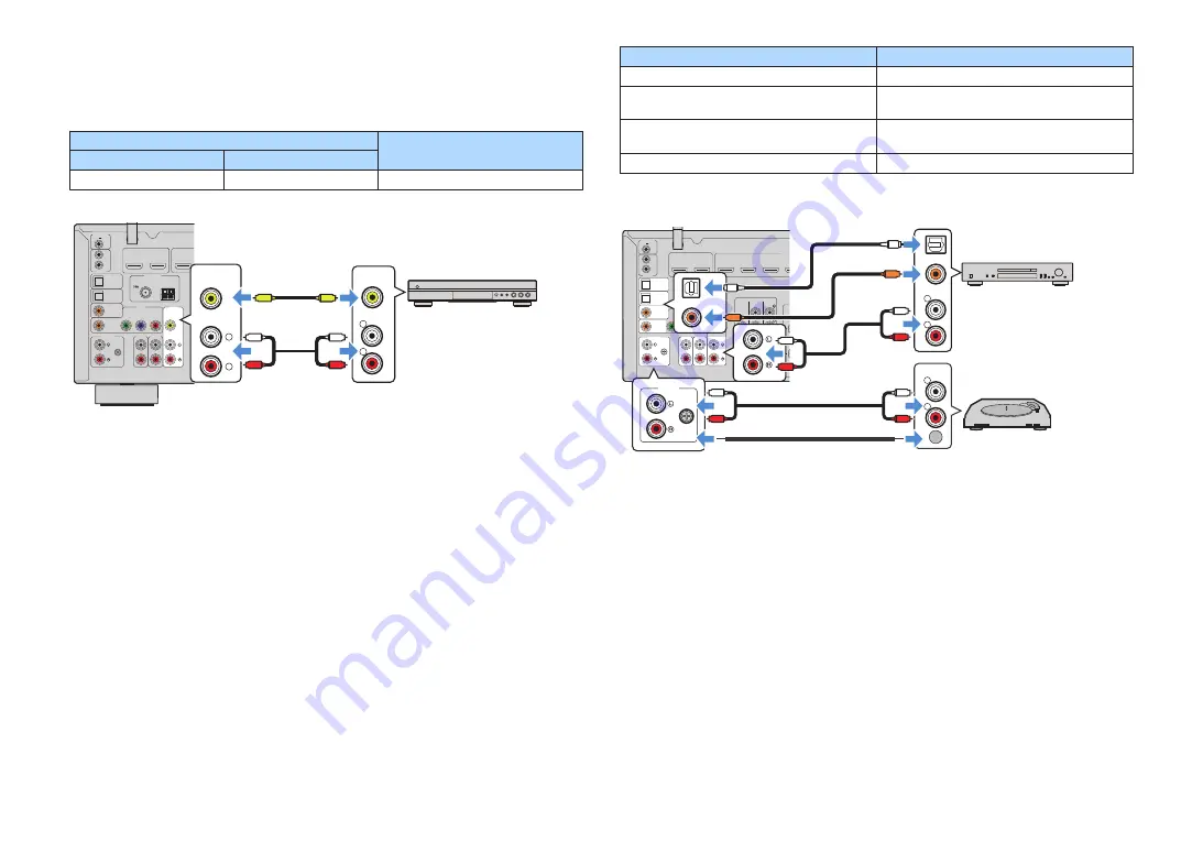
VIDEO (composite video) connection with a video
device
Connect a video device to the unit with a video pin cable and a stereo pin cable.
Output jacks on video device
Input jacks on the unit
Video
Audio
Composite video
Analog stereo
AV 2 (VIDEO + AUDIO)
ANTENNA
FM
AM
AUDIO 4
AUDIO 5
OPTICAL
OPTICAL
COAXIAL
COMPONENT VIDEO
COAXIAL
AUDIO 1
AUDIO 2
AUDIO 3
AV 1
AV 2
P
B
Y
P
R
1
1
2
ARC
VIDEO
CENTER
TRIGGER OUT
REMOTE
12V
IN
OUT
0.1A
HDMI OUT
PHONO
GND
HDCP2.2
(
)
(1 MOVIE)
( 7 TV )
( 3 MUSIC )
( 2 RADIO )
R
L
VIDEO
L
R
VIDEO
L
R
L
R
V
V
The unit (rear)
AV 2 (AUDIO) jacks
AV 2 (VIDEO) jack
Video output
(composite video)
Audio output
(analog stereo)
Video device
NOTE
If the combination of video/audio input jacks available on the unit does not match your video device, change
its combination according to the output jacks of your device. For details, see the following:
▪ “Combining audio of another input source with video of the current input source” (p.143)
n
AUDIO connection with an audio device such as a CD
player
Connect audio devices such as CD players and MD players to the unit. Depending on
the audio output jacks available on your audio device, choose one of the following
connections.
Audio output jacks on audio device
Audio input jacks on the unit
Digital optical
AUDIO 1–2 (OPTICAL)
Digital coaxial
AUDIO 3 (COAXIAL)
AV 1 (COAXIAL)
Analog stereo
AUDIO 4–5 (AUDIO)
AV 2 (AUDIO)
Turntable (PHONO)
PHONO
ANTENNA
FM
AM
AUDIO 4
AUDIO 5
OPTICAL
OPTICAL
COAXIAL
COMPONENT VIDEO
COAXIAL
AUDIO 1
AUDIO 2
AUDIO 3
AV 1
AV 2
P
B
Y
P
R
HDMI (
1
1
2
1
2
2
3
4
ARC
VIDEO
ZONE OUT
SUBWOOFER
FRONT
CENTER
SUR. BACK
SURROUND
PRE OUT
ZONE 2
TRIGGER OUT
REMOTE
12V
IN
OUT
0.1A
HDMI OUT
PHONO
GND
HDCP2.2
(
)
(1 MOVIE)
(5 STB)
(6 GAME)
( 7 TV )
( 3 MUSIC )
( 2 RADIO )
R
L
COAXIAL
OPTICAL
R
L
PHONO
GND
PHONO
GND
OPTICAL
COAXIAL
R
L
L
R
L
R
L
R
C
C
O
O
The unit
(rear)
PHONO jacks
Audio output
(either digital optical, digital coaxial, or
analog stereo)
Audio device
AV 1-2 jacks
AUDIO 1-5 jacks
Ground lead
Audio output (PHONO)
Turntable
NOTE
▪ The PHONO jack of the unit is compatible with an MM cartridge. To connect a turntable with a low-output
MC cartridge, use a boosting transformer.
▪ Connecting the turntable to the GND terminal of the unit may reduce noise in the signal.
▪ “AUDIO1” is set as TV audio input at the factory. If you have connected any external device to the AUDIO
1 jacks, use “TV Audio Input” in the “Setup” menu to change the TV audio input assignment. To use the
SCENE function, you also need to change the input assignment for SCENE (7). For details, see the
following:
– “Setting the audio jack used for TV audio input” (p.130)
– “Registering a scene” (p.91)
En
32


