21
Tyros2
NITOR SPEAKER
RS-MS02
ER’S MANUAL
ENUNGSANLEITUNG
E D’EMPLOI
21.
PNC and EN Circuit Boards
21-A EN Circuit Board
(Time required: About 6 minutes)
21A-1 Separate the unit into the upper case assembly and the
lower case assembly. (See procedure 1.)
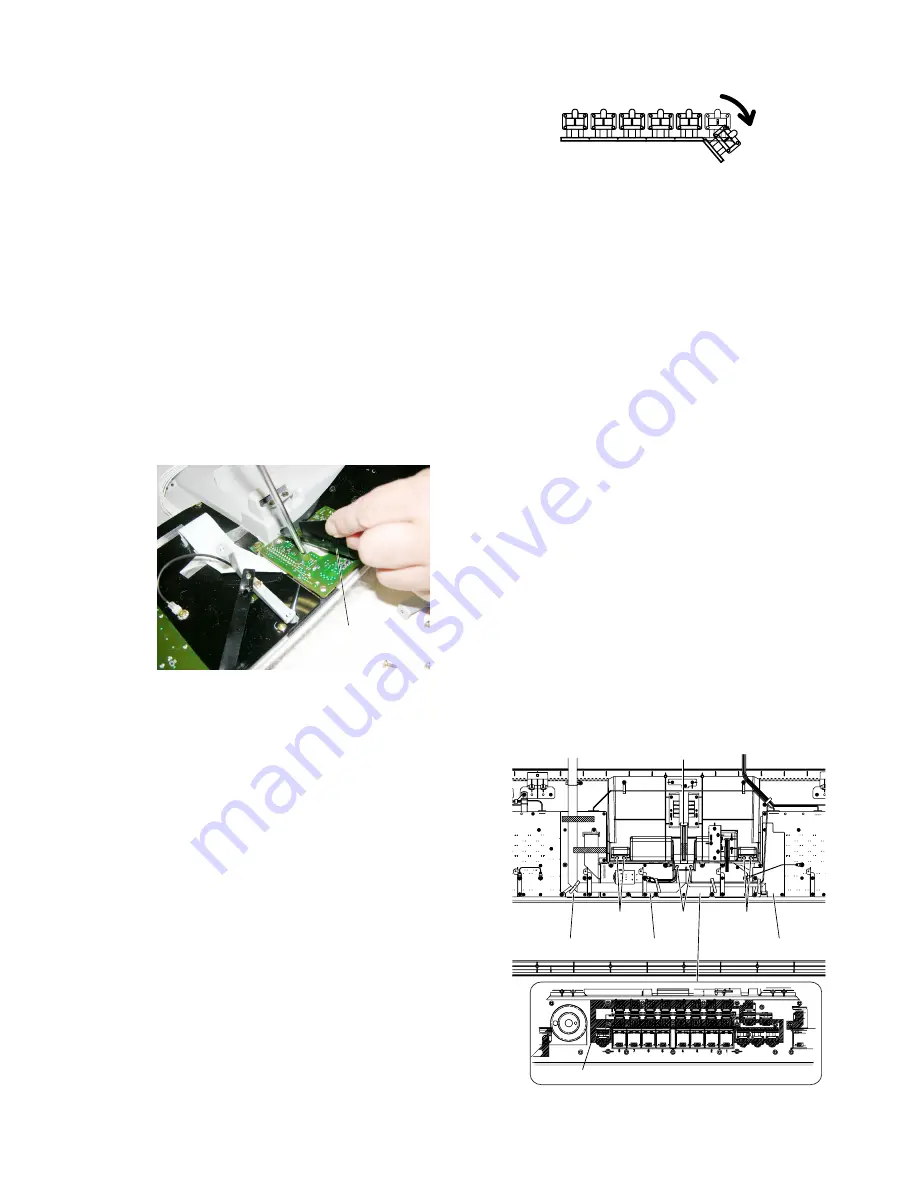
21A-2 Remove the screw marked [480F-A] and bend the
protection sheet C so that you can see the hole on the EN
circuit board.
Insert a screw driver (which is not sharp-edged) into the
hole, and push out the encoder knob marked [60].
(Fig.10,Fig.12,Fig.14A)
(It may damage the encoder knob to push continuously
the same point on it. So push out the encoder knob little
by little rotating it.)
21A-3 Remove the hexagonal nut marked [A]. The EN circuit
board can then be removed. (Fig.10,Fig.13)
*
The EN circuit board has been soldered to the PNC
circuit board by ribbon cables. When replacing it, use a
soldering iron.
(Fig.14A)
(Fig.11)
21-B PNC Circuit Board
(Time required: About 7 minutes)
21B-1 Separate the unit into the upper case assembly and the
lower case assembly. (See procedure 1.)
21B-2 Remove the EN circuit board. (See procedure 21-A.)
21B-3 Remove the three (3) screws marked [480E] and the
screw marked [470]. The two panel holders C can then
be removed. (Fig.10)
21B-4 Remove the twelve (12) screws marked [480F]. The PNC
circuit board can then be removed.
*
Note for the panel button replacement
The replacement part of the panel button marked [660] is
sixfold.
When replacing these buttons, separate an unnecessary
piece from the replacement part. (Fig.11)
As for the location of the multifold button, do not
arrange and use some single buttons.
*
When installing the PNC circuit board, place the
vibration-proof sheet C in between the circuit board and
the panel buttons.
Also, place the protection sheet C on the reverse side of
the circuit board. Then, tighten the screws. (Fig.14)
22.
MICVR Circuit Board
(Time required: About 5 minutes)
22-1
Separate the unit into the upper case assembly and the
lower case assembly. (See procedure 1.)
22-2
Remove the VR knob marked [40] and the VR knob
marked [50]. (Fig.12)
22-3
Remove the five (5) screws marked [480G]. The MICVR
circuit board can then be removed. (Fig.10)
23.
USB Circuit Board
(Time required: About 4 minutes)
23-1
Separate the unit into the upper case assembly and the
lower case assembly. (See procedure 1.)
23-2
Remove the four (4) screws marked [480H]. The USB
circuit board can then be removed. (Fig.10)
24.
Wheel Assembly
(Time required: About 4 minutes)
24-1
Separate the unit into the upper case assembly and the
lower case assembly. (See procedure 1.)
24-2
Remove the four (4) screws marked [480I]. The wheel
assembly can then be removed. (Fig.10)
25.
Power Switch
(Time required: About 4 minutes)
25-1
Separate the unit into the upper case assembly and the
lower case assembly. (See procedure 1.)
25-2
Remove the two (2) screws marked [480J]. The power
switch can then be removed. (Fig.10)
[620A]
Protect Sheet R Protect Sheet C
Stay Angle
Vibration-proof Sheet
Protect Sheet L
[620B]
[620B]
(Fig.14)
[620]: Bind Head Tapping Screw-B 3.0X12 MFZN2B3 (WE998100)
Protect Sheet C


