42
Chapter 4—Connections and Setup
01V96—Owner’s Manual
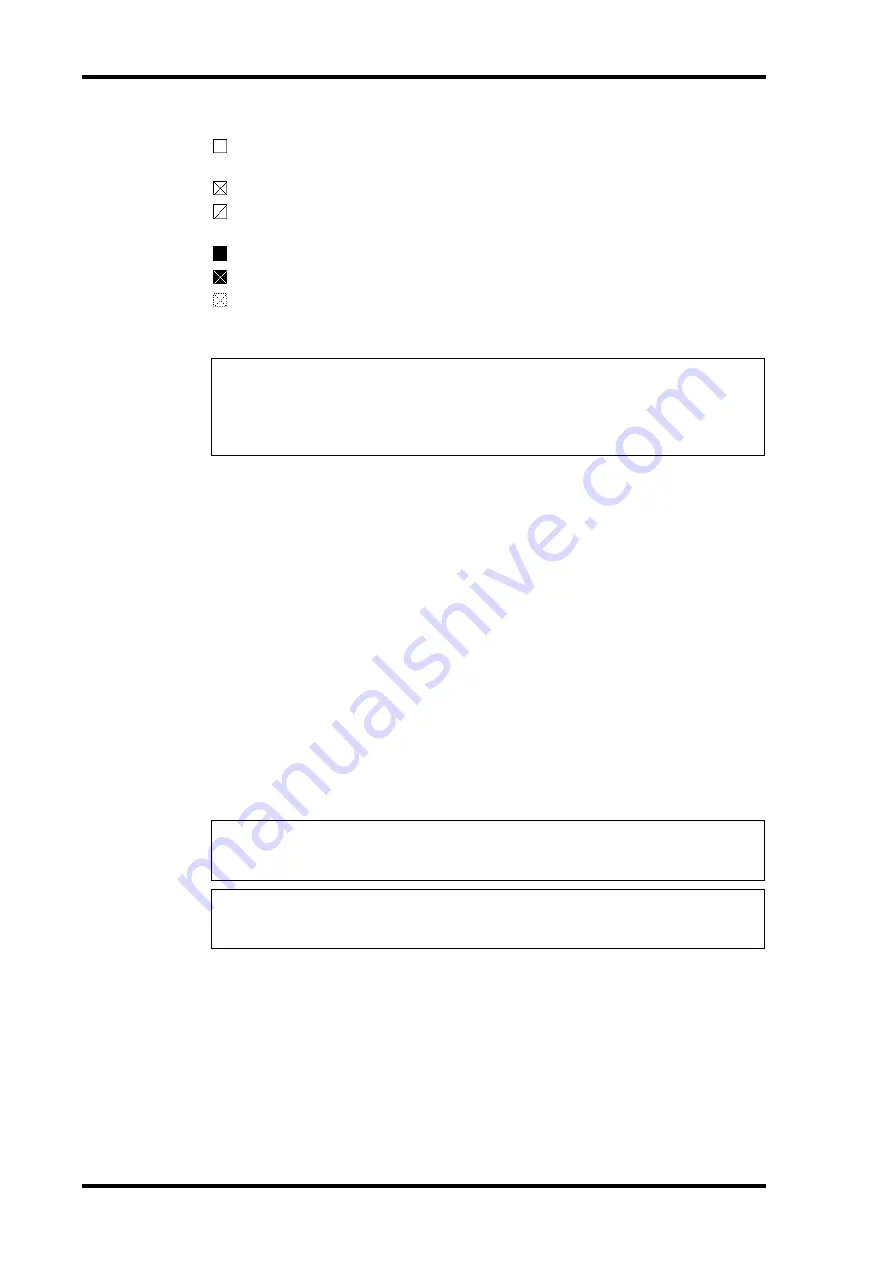
The source select button indicators are explained below:
A usable wordclock signal is present at this input, and it is in sync with the current
01V96 internal clock.
No wordclock signal is present at this input.
A usable wordclock signal is present at this input, but it is out of sync with the current
01V96 internal clock.
This input is the currently-selected wordclock source.
This input was selected as the wordclock source, but no usable signal was received.
Either this input is not receiving wordclock, or else it cannot be used with the cur-
rently-installed I/O card.
2 Use the cursor buttons to move the cursor to a source, then press [ENTER].
The following are possible wordclock sources:
•
SLOT
.............................. These buttons select the inputs from the digital I/O card
installed in the slot as the wordclock source. Inputs are selected
in pairs (odd and even numbers in this order). The SLOT TYPE
column displays the names of any installed I/O card. The num-
ber of pairs depends on the type of I/O card installed.
•
adat
................................ These buttons select the inputs from the ADAT IN connector
on the rear panel. Inputs are selected in pairs (odd and even
numbers in this order).
•
WC IN
............................ This button selects the wordclock signal input at the WORD
CLOCK IN connector on the rear panel.
•
2TRD
............................. This button selects the 2TR IN DIGITAL input as the word-
clock source.
• INT 44.1k, INT 48k
INT 88.2k, INT 96k
..... These buttons select the internal clock generator as the word-
clock source. The 01V96 will function as the wordclock master.
Tip:
• The FS box displays the sampling frequency at which the 01V96 is currently operating.
• The SLOT TYPE column displays the names of any installed I/O card.
• The IN and OUT columns indicate the number of input and output channels available for
each installed I/O card.
Note:
To transfer data at higher sampling frequencies (88.2 kHz or 96 kHz) between the
01V96 and connected external devices, you need to set the data transfer format. For more infor-
mation, see page 72.
Tip:
If wordclock transfer is interrupted while the 01V96 (being used as a slave unit) is receiv-
ing the clock signal, the unit automatically switches to the closest internal clock signal (INT
44.1k, INT 48k, INT 88.2k, or INT 96k).
Summary of Contents for 01V96
Page 1: ...E Owner s Manual Keep This Manual For Future Reference ...
Page 46: ...46 Chapter 4 Connections and Setup 01V96 Owner s Manual ...
Page 96: ...96 Chapter 7 Input Channels 01V96 Owner s Manual ...
Page 108: ...108 Chapter 8 Bus Outs 01V96 Owner s Manual ...
Page 130: ...130 Chapter 10 Input Output Patching 01V96 Owner s Manual ...
Page 160: ...160 Chapter 14 Internal Effects 01V96 Owner s Manual ...
Page 170: ...170 Chapter 15 Scene Memories 01V96 Owner s Manual ...
Page 184: ...184 Chapter 16 Libraries 01V96 Owner s Manual ...
Page 224: ...224 Chapter 18 MIDI 01V96 Owner s Manual ...
Page 329: ...Index 329 01V96 Owner s Manual ...


