


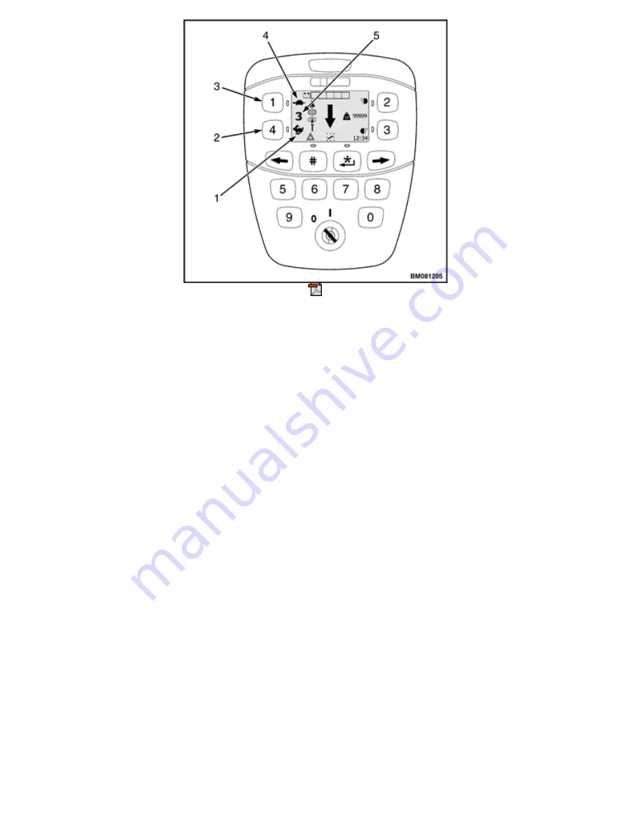
1.
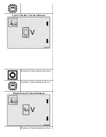
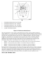
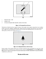
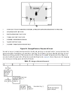
PERFORMANCE MODE INDICATOR - INCREASE
2.
PERFORMANCE MODE SOFT KEY - INCREASE
3.
PERFORMANCE MODE SOFT KEY - DECREASE
4.
PERFORMANCE MODE INDICATOR - DECREASE
5.
CURRENT PERFORMANCE MODE
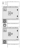
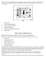
Figure 10. Performance Mode Controls
The current performance mode is shown on the Operating Screen. There are four available performance
modes, numbered 1, 2, 3, and 4. Performance mode 4 provides the maximum performance. If passwords are
enabled, the last active performance mode on the truck is displayed on the screen when the truck is powered
On, unless the current operator has been assigned a lower available performance mode. The maximum
performance mode allowed for each operator is set by the Supervisor or Service Technician during the
Add/Remove Password section of Truck Setup. See the Password Screen topic for more information.
Depending on the maximum performance mode allowed, it may be possible for the operator to use the
Performance Mode soft keys on the Display Panel to change the current performance mode.
•
MODE 4 - This is the highest performance mode. Other modes are a lower percentage of Mode 4.
•
MODE 3 - Top speed is the same as Mode 4. Acceleration is 80 percent of Mode 4.
•
MODE 2 - Top speed is 80 percent of Mode 4. Acceleration is 70 percent of Mode 4.
•
MODE 1 - Top speed is 60 percent of Mode 4. Acceleration is 60 percent of Mode 4.
Pressing the "Hare" soft key,
4
, increases the current mode and pressing the "Tortoise" soft key,
1
, decreases
the current mode, assuming performance mode change is available to the current operator. The performance
mode can be changed only when both the hydraulic and direction controls are in Neutral and the truck is
stopped. If a performance mode change is attempted at a time when either of these conditions is not met, the
newly selected mode will flash and the change will not occur until the necessary conditions are met.
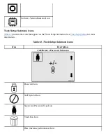
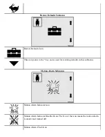
STATUS AND WARNING ICONS
Summary of Contents for ERC030VA
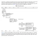
Page 8: ...Figure 3 Supervisor Flowchart Sheet 1 of 4 ...
Page 9: ...Figure 3 Supervisor Flowchart Sheet 2 of 4 ...
Page 10: ...Figure 3 Supervisor Flowchart Sheet 3 of 4 ...
Page 11: ...Figure 3 Supervisor Flowchart Sheet 4 of 4 Table 1 Supervisor Menu Flowchart A B C D E F G H ...
Page 21: ...Hydraulics Icon Alert Screens Cycle the Key Secure Battery Release Park Brake ...
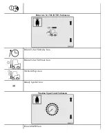
Page 22: ...Operator Out of Seat Release Pedal Release Hydraulic Input Traction Switch ...
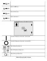
Page 23: ...Hydraulic Switch Temperature Too High Lift Limit Charge Battery ...
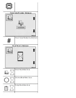
Page 26: ...Display Title Screen Status Title Screen Truck Setup Title Screen ...
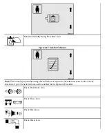
Page 105: ...Figure 71 Steering Wheel Number of Turns Valid Entry ...


