background image

28

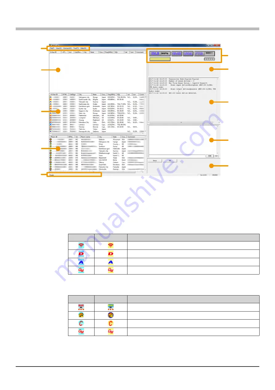
WIRES-X Software Main Screen

On the left side of the main screen is displayed the list of the active node stations and the active rooms is displayed. On 

the right side the operational status of the portable node station is displayed.

Group window

Menu bar

User monitoring
window

Status indicators

Function window

Log window

Chat window

Active node

window

Active room

window

Status bar

Menu bar

:


Calls the WIRES-X software main functions.

For details on each menu, refer to “Main Menu” (page 73) of the WIRES-X Connection Kit 

HRI-200 Instruction Manual.

Group window

:


Displays active nodes and rooms arranging the list based on the setting.

Active node

window

:


Active WIRES-X nodes are listed. The node station type and connection status are indicated 

by icons.


Node Icons

Idling

Connecting

Type

Portable Digital Node Station
Digital Node Station
Analog Node Station
GM Node Station

Active room 

window

:


Active WIRES-X rooms are listed. The room type and connection status are indicated by icons.


Room Icons

Idling

Connecting

Type

Open room (Only the Digital Nodes may be connected)
Open room
Closed room
GM room

Status bar

:


Displays information such as the WIRES-X software status and descriptions of a menu item 

pointed by the cursor.

For details, refer to “

Displaying the operating instructions

” 

page 90

of the WIRES-X 

Connection Kit HRI-200 Instruction Manual.

Summary of Contents for Wires-X

Page 1: ...Wide Coverage Internet Repeater Enhancement System WIRES X Portable Digital Node Function Instruction Manual Please read this Instruction Manual carefully for appropriate procedure ...

Page 2: ...nload the USB device driver from YAESU website and install it to a PC Refer to page 9 for details Update the firmware of the transceiver Download the latest firmware of the transceiver from our website and update the firmware of the transceiver for the Portable Digital Node station Refer to page 9 for details Connect the transceiver and the PC Connecting the transceiver and the PC with the designa...

Page 3: ... Portable Node 18 Connecting to a node or a room on the Internet 20 Communicating with other station 24 Disconnecting from the node or room 24 Closing the WIRES X software 24 Using the Portable HRI Mode 26 Connecting the transceiver and the PC 26 Starting the WIRES X software 26 Starting the transceiver in special mode 26 Connecting a node or a room by operating the WIRES X software on the PC 26 C...

Page 4: ...n SCU 19 USB Connection Cable FT2D and a PC with WIRES X Software and Internet connection Two forms of WIRES X Access are supported Access Point and Direct Operation In Access Point the Portable Node station FT2D can be used to communicate On Air and relay nearby local C4FM digital transceivers while simultaneously connected with the Internet WIRES X digital rooms and digital node stations In Dire...

Page 5: ...er the Access Point or the Direct Operation may be activated Access Point Portable HRI Mode In this mode WIRES X C4FM and Analog communications are made via another local C4FM transceiver communicating on frequency with the USB connected FT2D Node Station The FT2D Node Station relays the local C4FM and Analog signals to the internet and transmits the internet Node and Room signals to the local sta...

Page 6: ...GB or more of available space RAM 2 GB or more Display resolution 1366 x 768 16 bit high color or higher 32 bit true color is recommended USB port USB 2 0 Full Speed LAN port 100BASE TX 1000BASE T or Wi Fi IEEE 802 11 b or higher Audio Interfaces 1 1 Sound function is also required when using the Portable Digital Node mode or Portable HRI Mode Furthermore when communicating in Direct Operation in ...

Page 7: ...l in all the fields on the Member registration page and send it In the HRI 200 Serial Number RADIO ID field enter the RADIO ID of the transceiver used for the node station RADIO ID 5 digit alphanumeric ID unique to the transceiver The transceiver s RADIO ID is a combination of five letters and numbers Since the RADIO ID is distinguished between uppercase and lowercase letters of the alphabet pleas...

Page 8: ...1 500 or higher 2 Execute the Install exe file in the unzipped folder The WIRES X Installer window will appear 3 Click WIRES X Software Setup The Welcome to the WIRES X Setup Wizard window will appear 4 Click Next The License window will appear 5 Put a check mark in the I accept the terms in the License Agreement check box then click Next The Destination Folder window will appear 6 Confirm the des...

Page 9: ...he Completed the WIRES X Setup Wizard window will appear 8 Click Finish When WIRES X software installation has been completed properly the Wires X icon will appear on the Windows desktop 9 Click Close in the WIRES X installer windows Installation of the WIRES X software is complete ...

Page 10: ...ss the Press the DISP SETUP key 4 Rotate the DIAL to select 8 SOFTWARE VERSION then press the DISP SETUP key The firmware version of MAIN CPU and PANEL CPU DSP CPU will be displayed FTM 400XDR DE FTM 400DR DE 1 Press and hold the DISP SETUP key to display SETUP MENU 2 Touch RESET CLONE The firmware version of MAIN will be displayed on the top of the screen 3 Touch BACK 4 Touch TX RX 5 Touch DIGITA...

Page 11: ...s and PC as possible It is recommended to set the transmit output power of the transceiver as low as possible for the desired communication The connection is complete Communicating with digital or analog FM mode Portable HRI Mode Since the cable connection differs between Access Point and Direct Operation please refer to the following and make the connections according to the mode to be used When ...

Page 12: ...ect mode connection use the SCU 19 USB Connection Cable the CT 44 adapter one of the audio cables that are supplied in the SCU 39 Connection Kit sold separately as shown in the figure USB MIC DATA MIC SP Φ3 5 plug Gray Φ3 5 plug Gray The connection is complete ...

Page 13: ...Setting the Internet access security Only when Windows Security Alert screen appears If the Windows Security Alert window appears when starting WIRES X software click Allow access to allow Internet access from the WIRES X software Communication port setting When starting the WIRES X software for the first time the COM port setting window will appear Set the communication port with the transceiver ...

Page 14: ... is not displayed check the connection between the transceiver and the computer again 2 Click the ID Entry When activation is completed information on registration is automatically displayed for User ID Call Sign City State and Country 3 Click the OK The information of the User ID is saved on the computer and Settings window will appear On this screen the settings such as Comment of your station m...

Page 15: ...n operation default Unchecked DG ID Select the DG ID Digital Group ID number 00 to 99 default setting 00 When the DG ID number is set to 00 the node becomes an open node The subcode on the right can be set from 00 to 26 When DG ID number is set to 00 and subcode is set to 00 relay C4FM digital signals of all DG ID numbers When DG ID number is set to 00 and subcode is set from 01 to 26 C4FM digital...

Page 16: ...It takes about 10 minutes for the setting to be reflected in the node list default Unchecked This is the only item that may be set when using Access Point in the Portable Digital Node Mode 3 Click the OK The Transceiver window closes and the Main Screen will appear When a microphone is connected or built in the PC there may be cases where the sound around the PC is relayed be sure to remove the mi...

Page 17: ... News Station feature or the GM feature Setting the transceiver Access Point only When using the Access Point it is necessary to set the node station transceiver parameters such as operating fre quency and DG ID number on the portable node station transceiver When using the Direct Operation it is not necessary to set the frequency and parameters on the transceiver just proceed to Start operation o...

Page 18: ...r Since the transmit and receive DG ID number is TX 00 and RX 00 it operates as an open node and is accessible from all transceivers using C4FM digital mode When using a portable node station to be accessed only by the specific members set the transmit and receive DG ID to a number other than 00 In the Access Point if the receive DG ID is set to other 00 set the transmit DG ID number to the same D...

Page 19: ...cted to the PC and the WIRES X software has not been established so check the cable connection and USB driver installation To cancel the connection press and hold the X key 2 When the operation of the portable node is started the X icon changes from blinking to lit and the Node ID and the city of its own station are displayed Depending on the history of the previously connected node on the interne...

Page 20: ...s the BACKTRACK screen DISP key Enters the Set mode DISP key Press and hold Displays the frequency display screen V M key Displays the Function Menu Screen F MW Selects the Transmission Power Level TX PWR in the Function Menu Screen Selects Speaker Mute A B key Disconnects a node or a room on the Internet BAND key Press and hold Some setting items in the set mode are automatically set for the Port...

Page 21: ...tablished the IDLE indicator will change to the NET indicator and the User ID of the connected Node station or Room is displayed Connected will appear on the LCD of the portable node station s transceiver or the transceiver accessing the portable node station in WIRES X mode Room Pop up Window When connecting to the room a window will pop up displaying the operational status of the room For detail...

Page 22: ... establish the connection while talking Touch or to download and display 20 rooms or nodes at a time Touch TOP to return to the first 20 rooms or nodes Once connection is successfully established Connected will appear on the LCD If connection is unsuccessful an error message appears and the screen returns to the list of nodes and rooms Searching by node or room ID 1 Touch SEARCH DIRECT Displays th...

Page 23: ...nection Once connection is successfully established Connected will appear on the LCD If connection is unsuccessful an error message appears and the screen returns to the list of nodes and rooms If connection is unsuccessful an error message appears and the screen returns to the list of nodes and rooms Connecting to registered nodes or rooms to the category list 1 Touch SEARCH DIRECT Displays the c...

Page 24: ...ed to a node ID or a room ID on the Internet it appears and flashes at the bottom of the screen Touch the flashing node ID or room ID to start connection and once connection is established the menu list of the node room you are connected to will appear If connection is unsuccessful an error message appears and the name flashes again Specifying the DTMF ID of the node or room you want to connect to...

Page 25: ...meter does not swing In the Access Point when setting the receive DG ID number to except for 00 set the transmit DG ID number to the same number Note that sets to a different number will not work properly When setting the receive DG ID number to 00 and set the transmission DG ID number to anything other than 00 the voice of all received C4FM digital station will be heard on the speaker but for the...

Page 26: ...st 2 Touch ADD 3 Touch the desired category The name of the node or room you are currently connected to is added to the list of the registered node and room lists If the selected category is already registered with the same node or room a beep sounds and it will not register 4 Press the BACK key twice to return to the connection screen ...

Page 27: ...e set operation mode it is displayed on the frequency display as follows Access Point WIRES X NODE Direct Operation DIRECT To return the transceiver to the normal mode repeat procedure 1 in the above The portable station transceiver cannot use the News Station feature or the GM feature Connecting a node or a room by operating the WIRES X software on the PC On the WIRES X software main screen may b...

Page 28: ...ot transmit radio waves so the PO meter does not fluctuate 2 Release the PTT switch to return to receive mode The TX BUSY LED lights green while receiving communication from the other station on the Internet but the S meter does not fluctuate Confirming the location of the other station When latitude and longitude data is included in the signal of the other station the distance and direction of th...

Page 29: ...ctive nodes and rooms arranging the list based on the setting Active node window Active WIRES X nodes are listed The node station type and connection status are indicated by icons Node Icons Idling Connecting Type Portable Digital Node Station Digital Node Station Analog Node Station GM Node Station Active room window Active WIRES X rooms are listed The room type and connection status are indicate...

Page 30: ...receives reception of a digital signal whose DG ID number matches and relays it to other node stations or rooms via the Internet Transmission timeout timer When sending it counts down and displays the remaining time Up to 3 minutes until automatic transmission stops User monitoring window Displays the information below the status indicators of the digital Node station mobile or fixed that is acces...

Page 31: ...ode page 32 according to the mode you are using Adjusting Audio Level in the Access Point Portable HRI Mode Audio level adjustment should be done with no connection to the node station or room Receive audio level adjustment PC microphone input level Adjust the volume level so that the VOL bar graph is halved by turning the VOL knob of FT2D then make the following adjustments Also when using FT2D a...

Page 32: ...DG ID number as the Portable Digital Node station move the Slider to adjust so that the peak does not over the dotted line I f t h e m i c r o p h o n e i n p u t i s m u t e d c l i c k t h e i c o n on the right side of the slider to cancel mute 8 Press the OK button several times to close all Windows setting screens Completes the microphone input level adjustment of the personal computer Contin...

Page 33: ... e s p e a k e r o u t p u t i s m u t e d c l i c k t h e i c o n at the bottom of the slider to release the mute If the audio level of the transmission is too high or too low the sound may be distorted 5 Click the TX to stop transmits 6 Click the button at the top right of the Volume Mixer window to close The audio level adjustment of Access Point is completed Adjusting Audio Level in the Direct...

Page 34: ...lect area Waveform monitor is enabled 3 Click the Sound Property The WINDOWS Sound window opens 4 Click the Recording tab in the WINDOWS Sound window 5 Click Microphone then click the Properties button The microphone properties will open ...

Page 35: ...le while the waveform displayed on the waveform monitor does not exceed the dotted line or the peak of the waveform does not collapse 8 Click the Listen tab and check Listen to this device Depending on your computer there may be no Listen tab In that case please proceed to step 9 as it is 9 Press the OK button several times to close all Windows setting screens The microphone input level adjustment...

Page 36: ...peaker will be easy to hear When adjustment is completed click the Start button again to stop the test sound I f t h e s p e a k e r o u t p u t i s m u t e d c l i c k t h e i c o n at the bottom of the slider to release the mute If the volume level of Speaker Headphone is decreasing adjust the volume so that it is easy to hear 4 Adjust the volume level of the microphone on the Volume Mixer scree...

Page 37: ... sound to the analog station Default setting Turn it off when you do Internet communication only in digital mode ON Audio output to the analog station Is displayed on the right side of the call sign of the screen Always turn on Internet communication when using the analog communication in the analog mode When set to OFF the other station operating in analog mode cannot hear this voice When set to ...

Page 38: ... can make settings such as transceiver screen display in use in Portable HRI Mode and turning off the TX BUSY lamp FT2D function key Switching between Access Point and Direct Operation Press the A B key BACKTRACK screeen compass screen Press the DISP key Direct Operation only Transmission sound monitor function on or off Press the V M key Direct Operation only SQL open Press the MONI key SQL level...

Page 39: ...produced without the permission of YAESU MUSEN CO LTD YAESU MUSEN CO LTD Tennozu Parkside Building 2 5 8 Higashi Shinagawa Shinagawa ku Tokyo 140 0002 Japan YAESU USA 6125 Phyllis Drive Cypress CA 90630 U S A YAESU UK Unit 12 Sun Valley Business Park Winnall Close Winchester Hampshire SO23 0LB U K ...

Reviews: