


11
Linear Amplifier Interconnections
Be sure that both the FTDX10 and VL-1000 are turned OFF, and then follow the installation recommendations
contained in the bellow illustration.
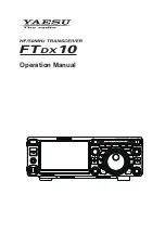
• VL-1000 Linear Amplifier Interconnections
• Refer to the VL-1000 Operating Manual for details regarding amplifier operation.
•
Do not attempt to connect or disconnect coaxial cables when your hands are wet.
DC IN
ANT
LINEAR
ALC 2
BAND-DATA 2
GND
GND
CONTROL
DC 48V IN
ANT 1
ANT 2
ANT 3
INPUT 2
Coaxial Cable (50 ohm)
Connect to “INPUT 2” of the VL-1000
HF/50MHz Antenna
“CT-118” Connection Cable (option)
• Interfacing to Other Linear Amplifiers
•
The TX GND OUT pin (pin 2) of the LINEAR jack is a transistor “open collector” circuit. It is capable of
handling positive relay coil voltages up to +60VDC at 200 mA or +30 VDC at 1 A.
• When using multiple linear amplifiers for different bands, you must provide external band switching of the
“Linear Tx” relay control line from the “TX GND OUT” line at the LINEAR jack.
Do not exceed the maximum voltage or current ratings for the “TX GND OUT” pin (pin 2) of the LINEAR jack.
This line is not compatible with negative DC voltages, or AC voltages of any magnitude.
DC IN
LINEAR
Antenna Cable (50Ω)
GND
GND
HF/50 MHz Antenna
RF OUT
RF IN
GND
EXT ALC
TX GND
ANT
Summary of Contents for FTDX10
Page 1: ...Operation Manual...