Xylem Bell & Gossett e-80SCXL Series Instruction Manual Download Page 31

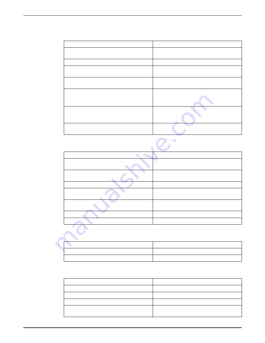
7.5  The thermal overload protection of the motor is triggered

occasionally, or after the pump unit has been running for a few minutes

Cause

Remedy

It is calibrated at a value too low in relation to the

rated current of the motor

Recalibrate

Input voltage outside the rated limits

Make sure the voltage values are correct

Unbalanced input voltage

Make sure the voltage of the three phases is

balanced

Incorrect working curve (flow rate greater that the

maximum permitted flow rate)

Reduce the required flow rate

Liquid too dense, presence of solid or fibrous

substances (pump unit overloaded)

• Reduce the density of the liquid and/or

• Remove the solid substance and/or

• Increase the size of the motor

Room temperature too high, exposure to sunlight

• Lower the temperature at the point od the

thermal overload protection and/or

• Protect against direct sunlight

Pump unit faulty

Send the pump unit to an authorized workshop for

testing

7.6  The pump unit runs but delivers too little or no liquid

Cause

Remedy

Motor turns in the wrong direction

Check the direction of rotation and change it if

necessary

Incorrect priming (there are air bubbles in the

suction pipe or in the pump unit)

Repeat the priming procedure

Cavitation

Increase the NPSH available in the system

Check valve locked in closed or partially closed

position

Replace the check valve

Foot check valve locked in closed or partially

closed position

Replace the foot valve

Delivery pipe throttled

Remove the throttling

Piping and/or pump unit clogged

Remove the clogging

7.7  The pump unit turns the other way when turned off

Cause

Remedy

Check valve faulty

Replace the check valve

Foot check valve faulty

Replace the foot valve

7.8  The pump unit produces excessive noise and/or vibrations

Cause

Remedy

Cavitation

Increase the NPSH available in the system

Unsuitable anchoring to the ground

Check the anchoring to the ground

Resonance

Check the installation

Anti-vibration joints not installed

Install anti-vibration joints on the suction and

discharge lines of the pump unit

7  Troubleshooting

Series e-80SCXL INSTRUCTION MANUAL

29

Summary of Contents for Bell & Gossett e-80SCXL Series

Page 1: ...INSTRUCTION MANUAL P2005589 A Series e 80SCXL...

Page 2: ......

Page 3: ...ist 12 4 2 Typical pump installation 13 4 3 Typical system installation 14 4 4 Foundation requirements 15 4 5 Requirements for setting the baseplate 16 4 6 Level the base on a concrete foundation 17 5...

Page 4: ...s been running for a few minutes 29 7 6 The pump unit runs but delivers too little or no liquid 29 7 7 The pump unit turns the other way when turned off 29 7 8 The pump unit produces excessive noise a...

Page 5: ...Safety WARNING The operator must be aware of safety precautions to prevent physical injury Operating installing or maintaining the unit in any way that is not covered in this manual could cause death...

Page 6: ...ols as shown in the following table Electrical hazard Magnetic fields hazard Electrical Hazard CAUTION 1 2 2 Safety instruction decals Alert symbol This safety alert symbol is used in manuals and on t...

Page 7: ...ction decals are always clearly visible and readable 1 2 3 User safety General safety rules These safety rules apply Always keep the work area clean Pay attention to the risks presented by gas and vap...

Page 8: ...micals or hazardous fluids that have come into contact with your eyes or your skin Condition Action Chemicals or hazardous fluids in eyes 1 Hold your eyelids apart forcibly with your fingers 2 Rinse t...

Page 9: ...e unfasten the product by removing any screws bolts or straps Use care around nails and straps 4 If there is any issue then contact a sales representative 2 2 Pump lifting WARNING Assembled units and...

Page 10: ...hand several times at least every three months Treat bearing and machined surfaces so that they are well preserved Refer to the drive unit and coupling manufacturers for their long term storage proce...

Page 11: ...he pump has two options for the mechanical seal Figure 2 Inside mechanical seal Figure 3 Outside mechanical seal Intended applications WARNING This product can expose you to chemicals including Lead w...

Page 12: ...al Viton Silicon Carbide Silicon Carbide Optional balanced outside seal Viton Silicon Carbide Silicon Carbide Operating temperature range F C 20 to 250 29 to 121 10 to 225 23 to 107 20 to 250 29 to 12...

Page 13: ...unit or motor assembly from falling Failure to properly support the pump and motor assembly could result in personal injury and or property damage 4 1 2 Pump location guidelines WARNING Assembled unit...

Page 14: ...to follow these instructions can result in serious personal injury or death or property damage Avoid serious personal injury and property damage Make sure that the flange bolts are adequately torqued...

Page 15: ...with a mesh hole diameter of no less than 0 25 in 0 64 cm Check that flexible piping is used on both the suction and discharge sides of the pump when you use an isolation base Check that a B G Triple...

Page 16: ...solation valve 9 Pipe from boiler chiller or converter 10 Cold water supply 11 B G Pressure Reducing Valve 12 B G Model 107A high capacity vent 13 B G 7 or 87 Air Vent 14 Drain valve Pressure relief v...

Page 17: ...nes When viewing the pump from the end of the base plate establish a vertical line through the pump flange center On both sides of this vertical line a line that starts at the pump flange center and e...

Page 18: ...hor bolt and a plain flat type W washer at each anchor bolt hole Otherwise the pump unit can shift Failure to follow these instructions can result in serious property damage and or moderate personal i...

Page 19: ...anchor bolts Use an anchor bolt for each anchor bolt hole provided and use plain flat type W washers with each anchor bolt Baseplate checklist You must fulfill these requirements before the baseplate...

Page 20: ...ed 2 5 F 1 4 C per minute You must follow these precautions before you start the pump Flush and clear the system thoroughly to remove dirt or debris in the pipe system in order to prevent premature fa...

Page 21: ...quickly reaches the correct discharge pressure 5 If the pump fails to reach the correct pressure perform these steps a Stop the driver b Prime the pump again c Restart the driver 6 Monitor the pump wh...

Page 22: ...Do not expose an idle pump to freezing conditions Drain all liquid that is inside the pump and the flush lines Failure to do so can cause liquid to freeze and damage the pump 5 5 Shut down the pump 1...

Page 23: ...efore you disassemble the pump for overhaul 6 2 2 Drain the pump CAUTION Allow all system and pump components to cool before you handle them to prevent physical injury 1 Close the isolation valves on...

Page 24: ...b If an inside seal remove the seal using a pair of screwdrivers to pry out the seal 7 Clean the seal box seal cap or gland and shaft CAUTION Avoid touching the faces of the seal and getting them dir...

Page 25: ...ith the rotating face up toward the motor until it contacts the snap ring b Install the seal seat with seal cap or gland with the gasket between the cap and the motor bracket over the end of the shaft...

Page 26: ...TC motor 1 2 3 Figure 11 Motor collar ring setting for IEC motor 1 Motor mounting surface 2 Collar ring 3 DC The collar ring is held in position on the motor shaft with set screws These set screws mus...

Page 27: ...e During reassembly pump shaft and impeller will be pulled back up into position by the tapered washer acting against the tapered groove in the coupler 4 After the seal is pre assembled onto the pump...

Page 28: ...ual loosen the bolts and repeat the tightening step 10 Slowly rotate the shaft by hand and check to see if any rubs occur a If no rubs occur prime and start the pump run for two minutes and determine...

Page 29: ...and service representative and be prepared to provide this information 1 Complete nameplate data of pump and motor 2 Suction and discharge pipe pressure gauge readings 3 Ampere draw of the motor 4 A...

Page 30: ...e RCD is activated Cause Remedy Motor leaking Check and repair or replace the motor Unsuitable type of differential Check the type of differential 7 4 The thermal overload protection of the motor is t...

Page 31: ...runs but delivers too little or no liquid Cause Remedy Motor turns in the wrong direction Check the direction of rotation and change it if necessary Incorrect priming there are air bubbles in the suc...

Page 32: ...sion vessel Pump unit oversized Contact Xylem or the Authorized Distributor 7 10 The pump unit never stops automatic start stop Cause Remedy The required flow rate s greater than the one expected Redu...

Page 33: ...Lower the room temperature Cooling fan of the motor clogged or damaged Clean or replace the cooling fan The pump unit starts up too frequently See Part 7 8 The frequency converter if present has not...

Page 34: ...paired or replaced Seller shall have no warranty obligations to Buyer with respect to any product or parts of a product that have been a repaired by third parties other than Seller or without Seller s...

Page 35: ...n a manner contrary to Seller s instructions for installation operation and maintenance d damaged from ordinary wear and tear corrosion or chemical attack e damaged due to abnormal conditions vibratio...

Page 36: ...gas utilities In more than 150 countries we have strong long standing relationships with customers who know us for our powerful combination of leading product brands and applications expertise with a...

Reviews: