


31
5-1-2
.
Wiring example
(1)
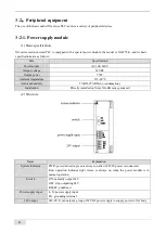
XG1 input wiring example
COM
X0
X2
X4
X6
X1
X3
X5
X7
COM0
Y1
Y3
Y4
Y6
Y0
Y2
COM1
Y5
Y7
1
2
3
4
5
6
7
8
9
10
11
12
13
14
15
16
17
18
19
20
(2)
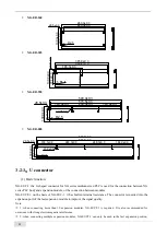
XG2 input wiring example
◼
NPN wiring
+24V
●
L+
X0+ X1+
X2
X3-
X6+ X7+ X10
M
X0- X1- X3+ X4+
X6- X7-
X4-
X5
+24V
●
L+
X0+ X1+
X2
X3-
X6+ X7+ X10
M
X0- X1- X3+ X4+
X6- X7-
X4-
X5
+24V
●
L+
X0+ X1+
X2
X3-
X6+ X7+ X10
M
X0- X1- X3+ X4+
X6- X7-
X4-
X5
红(棕) 蓝
蓝(蓝)
黄(黑)
红(棕)
DC24V
Switch button wiring example
2-wire (NO or NC) proximity switchwiring example 3-wire (NPN) proximity switch wiring example
◼
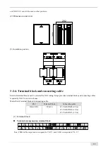
Differential mode
Differential wiring example
Note:
(1) In the left figure, the solid line part is NPN connection, and the
dotted line part is PNP connection.
(2) The PLC is generally equipped with a plug-in spring connector to
facilitate wiring when it leaves the factory. The length of the stripped
wire of this connector is required to be 1.5cm. When wiring, press the
yellow spring switch with a small screwdriver, insert the wire into the
corresponding jack, and release the spring switch.


