Installation Guide for C3-X60 Series Control Panel
an auxiliary output); C3-260 has four relays (by default, two used as control locks
and the other two used as auxiliary outputs); C3-460 has eight relays (by default,
four used as control locks and the other four used as auxiliary outputs).
The relays for auxiliary outputs may be connected to monitors, alarms, door bells,
etc. Auxiliary outputs are set through relevant access control software. For details,
please refer to
ZKAccess5.0 User Manual.
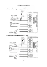
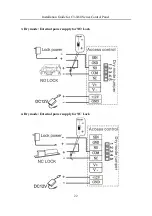
A lock relay can be connected in the dry and wet modes, while an auxiliary output
relay cannot. The following illustrates relay output connection with an example of
door connection.
1) An access control panel provides multiple electronic lock outputs. The COM and
NO terminals are applicable to the locks that are unlocked when power is connected
and locked when power is disconnected (that is NO lock). The COM and NC
terminals are applicable to the locks that are locked when power is connected and
unlocked when power is disconnected (that is NC lock).
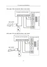
2) By setting the jumper terminal beside the lock relay, you can select the device
power supply or lock power supply for the lock (that is, the wet mode or dry mode).
Dry mode jumper setting:
Short 1-2 and 3-4, and the device power supply will be
used for the relay output.
Wet mode jumper setting:
short 2-3 and 4-5, and the lock power supply will be
used for the relay output.
Note
: The factory default jumping is set as dry mode.
3) To protect the access control system against the self-induced electromotive force
generated by an electronic lock at the instant of switching off/on, it is necessary to
connect a diode in parallel (please use the FR107 delivered with the system) with
the electronic lock to release the self-induced electromotive force.
20

