background image

8-96

Phaser 6280 Color Laser Printer Service Manual

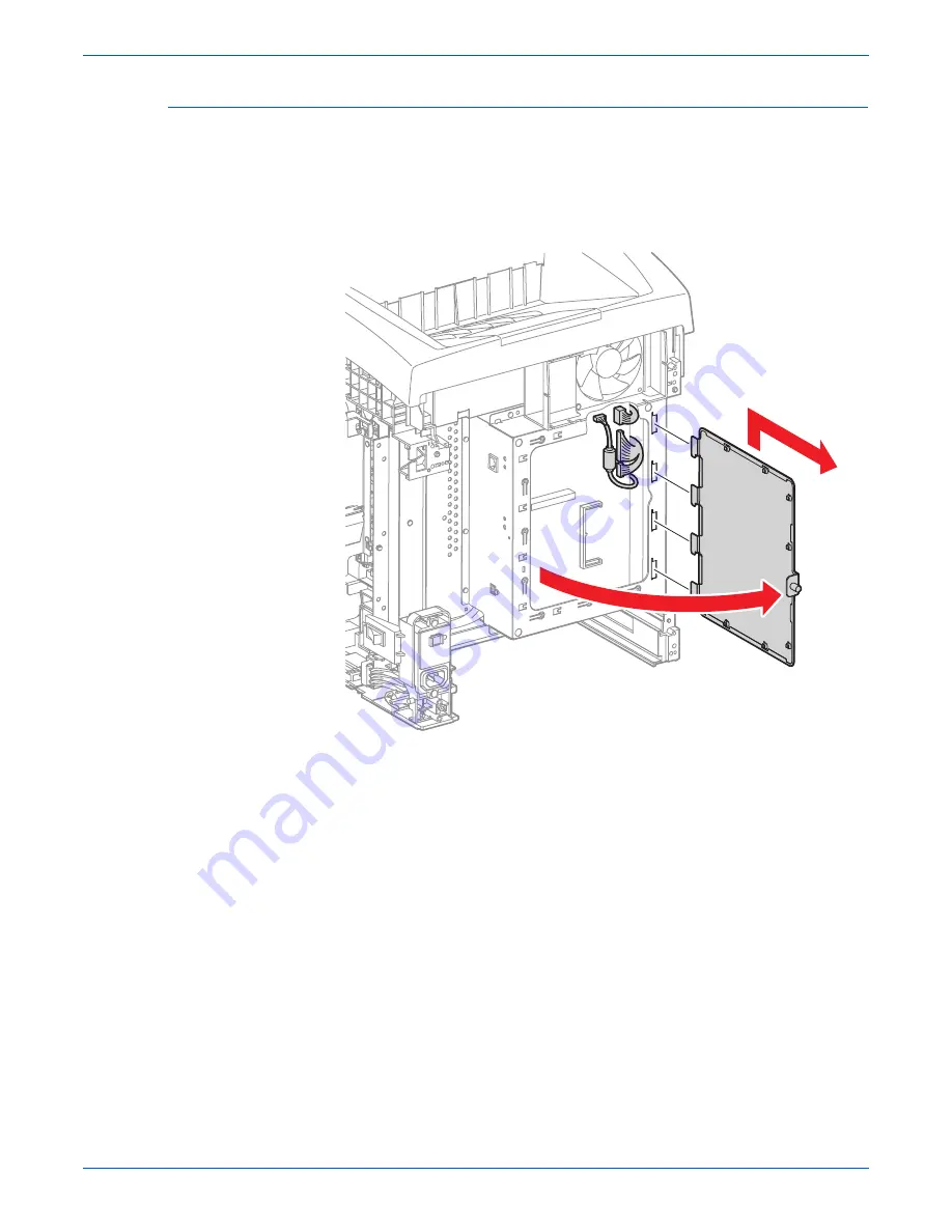
Service Parts Disassembly

Image Processor Board Shield Assembly (PL9.1.45)

1.

Remove the Rear Cover (page 8-12).

2.

Loosen the Knurling Screw (PL9.1.44) and open the Window Shield 
(PL9.1.21).

3.

Lift the Window Shield up to release the 4 tabs of the Window Shield from 
the holes on the I/P Board Shield (PL9.1.25).

s6280-242

Summary of Contents for Phaser 6280

Page 1: ...Phaser 6280 Color Laser Printer Phaser 6280 Service Manual...

Page 2: ......

Page 3: ...ing The following servicing instructions are for use by qualified service personnel only To avoid personal injury do not perform any servicing other than that contained in the operating instructions u...

Page 4: ...ted States and or other countries Adobe and PostScript are trademarks of Adobe Systems Incorporated in the United States and or other countries Apple Bonjour ColorSync EtherTalk Macintosh and Mac OS a...

Page 5: ...omplish a task A note can provide additional information related to a specific subject or add a comment on the results achieved through a previous action Caution A caution indicates an operating or ma...

Page 6: ...e printer Use caution to avoid personal injury Use caution or draws attention to a particular component Refer to the manual s for information It may take 30 minutes for the fuser to cool down Do not t...

Page 7: ...outlet If the product loses its ground connection contact with conductive parts may cause an electrical shock A protective ground connection by way of the grounding conductor in the power cord is esse...

Page 8: ...fore applying power to the unit under test to avoid potential shock After removing a static sensitive assembly from its anti static bag place it on a grounded conductive surface If the anti static bag...

Page 9: ...arning Labels Read and obey all posted warning labels Throughout the printer warning labels are displayed on potentially dangerous components As you service the printer check to make certain that all...

Page 10: ...are instructed to do so by a service procedure Servicing Mechanical Components When servicing mechanical components within the printer manually rotate the Drive Assemblies Rollers and Gears Warning Do...

Page 11: ...safety lifting and handling techniques when moving the printer Always move the printer separately from Tray 2 When shipping the printer repack the printer using the original packing material and boxe...

Page 12: ...ever there is no guarantee that interference will not occur in a particular installation If this equipment does cause harmful interference to radio or television reception which can be determined by t...

Page 13: ...ean Union regulations use shielded interface cables A signed copy of the Declaration of Conformity for this product can be obtained from Xerox The CE mark applied to this product symbolizes Xerox s de...

Page 14: ...codes generated by resident diagnostics Section 4 General Troubleshooting This section contains the operation of Power On Self Test POST and Service Diagnostics In addition this section includes trou...

Page 15: ...Phaser 6280 Color Laser Printer Service Manual xiii...

Page 16: ...xiv Phaser 6280 Color Laser Printer Service Manual...

Page 17: ...Printer Options 1 8 Additional Memory 1 8 Duplex Unit 1 8 Hard Disk Drive 1 9 Optional 550 Sheet Feeder Tray 3 1 10 Maintenance Items 1 11 Consumables 1 13 Printer Specifications 1 14 Memory Specifica...

Page 18: ...Tray 2 2 16 Paper Feeder 2 21 Tray 1 MPT Registration 2 23 Fuser 2 28 Transfer Unit 2 30 Laser Unit 2 31 Print Cartridge 2 33 Main Drive 2 35 Electrical 2 37 Duplex Unit 2 43 Tray 3 Optional 550 Sheet...

Page 19: ...54 Fuser Error 3 55 Ready Fuser Life 3 57 Print Cartridge Near Life Yellow Magenta Cyan Black 3 58 Check Cartridge Yellow Magenta Cyan Black 3 59 Replace Print Cartridge Yellow Magenta Cyan Black 3 61...

Page 20: ...eeder Motor Error 3 126 Laser Error 3 129 Optional 550 Sheet Feeder Error 3 130 Duplex Error 3 132 Door A Open 3 134 ADC Sensor Error High Density 3 135 ADC Sensor Error Low Density 3 139 Environmenta...

Page 21: ...4 Abnormal Noise when Power is Turned On 4 74 Abnormal Noise During Printing 4 77 Electrical Noise 4 80 AC Noise 4 81 Operating System and Application Problems 4 83 Windows 2000 Windows XP Windows Ser...

Page 22: ...Image or Ghosting 5 44 Background Contamination 5 46 Skew 5 48 Damaged Paper 5 51 Unfused Image 5 54 Color Registration 5 56 6 Adjustments and Calibrations Adjustments 6 2 Color Registration 6 2 Print...

Page 23: ...3 8 26 Bottom Plate PL2 1 20 8 27 Tray 1 MPT No Paper Actuator PL2 1 26 8 28 Tray 2 Retard Roll PL2 2 17 8 29 Paper Feeder 8 30 Tray 1 MPT Feed Solenoid PL3 1 3 PL3 1 99 8 30 Tray 1 MPT Roll PL3 1 8 8...

Page 24: ...l 550 Sheet Feeder 8 100 Optional 550 Sheet Feeder PL12 1 1 8 100 Tray 3 Left Cover PL12 1 2 8 101 Tray 3 Cover PL12 1 4 8 102 Tray 3 Turn Clutch PL12 1 5 8 103 Tray 3 Feed Clutch PL12 1 6 8 104 Tray...

Page 25: ...iring Diagrams 10 8 Map 1 Electrical and Drive 10 9 Map 2 Laser Unit Feeder Assembly 10 10 Map 3 Image Processor Board and Dispenser 10 11 Map 4 LVPS and MCU Boards 10 12 Map 5 Duplex Unit 10 13 Map 6...

Page 26: ...xxiv Phaser 6280 Color Laser Printer Service Manual Table of Contents...

Page 27: ...er General Information In this chapter Printer Introduction and Overview Printer Configurations Parts of the Printer Printer Options Maintenance Items Consumables Printer Specifications Controller Fun...

Page 28: ...550 Sheet Feeder is available as an option Auto duplexing is available and no tools are required to install the Duplex Unit A Hard Disk Drive is available for Secure Print Proof Print collation and fo...

Page 29: ...00 x 4 bit 600 x 600 x 1 bit 600 x 600 x 4 bit Print Speed Color Mono 26 31 26 31 Fonts Adobe PostScript 3 Fonts PCL6 Fonts Standard Standard Standard Standard Interface USB 2 0 Hi Speed Support Ether...

Page 30: ...General Information Parts of the Printer Front and Side Views 1 Tray 2 2 Tray 3 3 Tray 1 MPT 4 Front Cover Door A 5 Control Panel 6 Output Tray 7 Extender Cover 8 Top Cover 9 Front Cover Release Butt...

Page 31: ...Phaser 6280 Color Laser Printer Service Manual 1 5 General Information Rear View 1 Ethernet Port 2 USB Port 3 Power Cord Connector s6280 034 1 2 3...

Page 32: ...eep mode 2 Error LED Light On Error with print job blinking not user fixable On solid user fixable 3 Graphic Control Panel Display Displays printer settings status and messages 4 Menu Button Changes d...

Page 33: ...rint or in Power Saver mode Flashing Green Processing print job Red Error occurs can be fixed by user Flashing Red Error occurs cannot be fixed by user Mode Buttons Pressed at Power On Service Diagnos...

Page 34: ...Additional Memory The printer features one slot that accepts 512 MB or 1024 MB of DDR2 DIMMs Memory modules must meet the following characteristics 200 Pin DDR2 DIMM 8 chip type Unbuffered Non parity...

Page 35: ...aser Printer Service Manual 1 9 General Information Hard Disk Drive The Phaser 6280 supports a customer removable Hard Disk for Secure Print Proof Print collation and for storing additional fonts form...

Page 36: ...neral Information Optional 550 Sheet Feeder Tray 3 The Optional 550 Sheet Feeder increases the input capacity of the printer and can be attached to the printer underneath Tray 2 with 2 screws Note Onl...

Page 37: ...The listed items have limited life and require periodic replacement Note Print life is based on typical office printing and 5 coverage per color on 24 lb paper The 100 000 life is not guaranteed and...

Page 38: ...1 12 Phaser 6280 Color Laser Printer Service Manual General Information s6280 039 Optional 550 Sheet Feeder Feed Roller Tray 3 Optional 550 Sheet Feeder Retard Roller...

Page 39: ...CRUM Customer Replaceable Unit Meter to record the information CRUM counts the amount of remaining toner When toner empty is detected Life End status will be sent to indicate toner empty Life ratings...

Page 40: ...month Maximum 60 000 PV month For Duplex prints prints on the front and back sides of paper are counted as 2 PV Maximum PV is 2 000 PV day Color Medium Cyan Magenta Yellow and Black Print Cartridges R...

Page 41: ...230 V Engine 4 A or less Power Consumption Power Saver Mode 9 W or less 110 V 3 9 W 220 V 4 3 W Standby Mode Fuser On 95 W or less 110 V 64 3 W 220 V 68 4 W Color Printing Duplex 460 W or less 110 V...

Page 42: ...tter 21 26 14 18 A4 21 25 14 17 A5 18 26 14 21 US Folio 18 23 13 16 Legal custom 18 21 12 15 Characteristic Specification Temperature Operating 10 to 32 C 50 to 90 F Standby 20 to 40 C 4 to 104 F Humi...

Page 43: ...ording The system is at Pause Cooling Fan The fan operates at low speed Control Panel Operation LCD Backlight On LED If printer is online Ready LED is turned On Power Saver Mode The printer enters int...

Page 44: ...nal in Ready state until a single page is printed and delivered to the output tray The following conditions are applied The Controller does not keep the print engine waiting The printer is at Standby...

Page 45: ...ches x 351 6 mm 13 8 inches Guaranteed Print Area 207 9 mm 8 2 inches x 347 6 mm 13 7 inches Skew 190 mm 1 2 mm Perpendicularity 114 5 mm 0 8 mm Parallelism Horizontal 180 mm 1 2 mm Vertical 234 mm 1...

Page 46: ...Width 400 mm 15 7 in 400 mm 15 7 in Depth 490 mm 19 3 in 490 mm 19 3 in Weight base printer with supplies 24 5 kg 54 0 lb 29 25 kg 64 5 lb Optional 550 Sheet Feeder Height 138 mm 5 4 in 138 mm 5 4 in...

Page 47: ...cations apply to any printer used as a table top printer 1 In order to function properly the printer must be placed on a surface with the following minimum dimensions 2 Mounting surface flatness must...

Page 48: ...ting specifications will void all guarantees of print quality and or performance Known problems that can occur as a result of exceeding the mounting surface specifications are Color to Color mis regis...

Page 49: ...S 182 x 257 mm Yes Yes Yes Custom Size Yes Yes Yes All trays support Custom sizes Tray 1 supports a wider range of Custom size dimensions than trays 2 and 3 Supported Paper Types and Weights Paper Typ...

Page 50: ...ported Envelopes Type Dimension Tray 1 MPT Tray 2 3 Duplex Envelope 10 4 12 x 9 5 in Yes No No Monarch Envelope 3 87 x 7 5 in Yes No No C5 Envelope 162 x 229 mm Yes No No DL Envelope 110 x 220 mm Yes...

Page 51: ...l Panel Job cancellation is not immediate Depending on the job size it may take a while to completely cancel Forced Output This function forces the printer to print the received data when the printer...

Page 52: ...eck box of this function Secure Print Store Print The printer holds print data including a user password 12 digits specified in the printer driver user name and document name in memory The data will n...

Page 53: ...r The printer prints only the first set of the print data including a user name and document name specified in the printer driver The user can keep or remove the data using the printer menu on the Con...

Page 54: ...kets DMO Toner Remaining Amount The CentreWare Internet Services IS and PrintingScout allow the printer to display toner remaining amount Print Cartridge Control Panel Display Print Cartridge Control...

Page 55: ...Firmware Update on page A 3 Note Boot Code can be updated via USB port only Diagnostics Two types of diagnostic functions are available 1 Auto Diagnostics The printer is checked when it is turned on...

Page 56: ...eral Information Information Pages Demo Page Demo Page provides sample of print for the Phaser 6280 Color Laser Printer The Demo Page is printed in color from selected paper tray The Demo page will be...

Page 57: ...Phaser 6280 Color Laser Printer Service Manual 1 31 General Information Configuration Page configuration ai...

Page 58: ...ipt CRD Version Default Paper Default Language Current Temperature Current Humidity Region Printer Options Duplex Unit 00 00 00 when installed Hard Disk when installed Paper Tray Tray 1 MPT Tray 2 3 P...

Page 59: ...d Document List Memory or Hard Drive is needed User can print the Stored Document List using Secure Print Proof Print feature The list can be printed on A paper size from default tray Job History Repo...

Page 60: ...rs and up to 42 fatal errors User can print the Error History Report default on A paper size from default tray using the printer menu in the Control Panel Jam Error log includes the following informat...

Page 61: ...ex print is counted as 1 and duplex print is counted as 2 including N up If an error has occurred after the one side printed properly during duplex printing it is counted as 1 Note Same data is stored...

Page 62: ...1 36 Phaser 6280 Color Laser Printer Service Manual General Information...

Page 63: ...pter Theory of Operation In this chapter Phaser 6280 Printer Operational Overview Printing Process Paper Path of the Printer Major Assemblies and Functions Printer Modes Printer Control Drive Transmis...

Page 64: ...four color CMYK process The tandem system consists of four color print cartridges C M Y and K which creates the toner image The following block diagram provides the sequence of events for the xerograp...

Page 65: ...finished toner image on the Drums is transferred onto the paper 5 Cleaning Print Cartridge Remaining toner on the drums is collected 6 Neutralization The Detack Saw neutralizes the charge on the paper...

Page 66: ...e Drum The BCR is a conductive roll which receives negative voltage from the High Voltage Power Supply HVPS and discharges a negative Direct Current DC voltage The Drum surface is uniformly and negati...

Page 67: ...n as the polygon mirror rotates which attaches the fixed mirror and lenses to the Scanner Motor of the Laser Unit Rear View Mirror Mirror Laser Diodes Laser Diode Board Lens Scanner Polygon Mirror Win...

Page 68: ...n Magenta Yellow and Black colors The area on the surface where the voltage potential drops due to exposure to the laser beam becomes the electrostatic latent image Laser Unit Laser Beams Laser Beam L...

Page 69: ...s called Toner Dispensation which is controlled by two processes Pixel Count Dispense Control PCDC and Automatic Density Control ADC The toner fed into the Developer and the carrier in the Developer a...

Page 70: ...ease potential is lower than the magnet roll while the potential is higher than the magnet roll at the area where the negative charge on the drum surface decreases The AC voltage shakes the Developer...

Page 71: ...ransferred onto the surface of the paper The toner is transferred onto the paper in the order of Y M C and K Transfer Drum Paper Drum Surface Black Toner Image Drum Surface Cyan Toner Image Drum Surfa...

Page 72: ...er Unit Belt The Transfer Unit is a conductive unit which receives positive voltage from the BTR After the negative charged toner image on the Drum surface is drawn by the positive charge on the belt...

Page 73: ...toner Cleaning Roll The Cleaning Roll contacts the surface of the BCR collecting the excess toner by scraping off toner Charge Cleaning When the Drum is charged by the BCR any excess charge hinders t...

Page 74: ...n the paper via the Belt The Detack Saw a metal sheet secured at the ground level is installed at several millimeters away from the back side of the belt s6280 056 Negative Electric Charge Positive El...

Page 75: ...is fused onto the paper by the combination of heat and pressure Cleaning A cleaning blade in the Print Cartridge scrapes off toner remaining on the drum surface after transfer has occurred Then the l...

Page 76: ...d Prevention Multiple Sheet Feed Prevention Multiple Sheet Feed Prevention 550 Sheet Feeder Tray 3 Motor Drive Solenoid MPT Roll Turn Roll Motor Drive Clutch Feed Roll Turn Roll 250 Sheet Standard Tra...

Page 77: ...te Heat Roller Fuser Duplex Roller Duplex Module Duplex Roller Duplex Module Duplex Jam Sensor Duplex Module Belt Transfer Unit Regi Roller Metal Registration Regi Roller Rubber Registration Regi Sens...

Page 78: ...he printer configuration Tray 2 Paper Feeder Tray 1 MPT Registration Fuser Transfer Unit Laser Unit Print Cartridge Main Drive Electrical Duplex Unit Tray 3 Optional 550 Sheet Feeder Tray 2 Tray 2 Lef...

Page 79: ...e position to detect the paper size The paper size is detected at the End Guide position Note Refer to Paper Size Detection on page 2 52 for detailed information on paper size switches and paper size...

Page 80: ...the Bottom Lock Oneway Gear c When the tray is pushed until it stops the Bottom Lock Lever is pressed down by the Support Nudger in the Sheet Feeder d The Bottom Lock Lever actuates the Bottom Lock L...

Page 81: ...s which can cause a multiple feed or a jam The Nudger Roller feeds the sheets to a position between the Feed Roller and the Retard Roller Normally when only one sheet is fed both the Feed Roller and R...

Page 82: ...to extra force from feeding two sheets this process allows the upper sheet to pass by as the lower sheet is stopped by the friction with the Retard Roller at rest The Retard Roller is pushed toward t...

Page 83: ...erates Tray 2 Feed Clutch The Feed Clutch transmits drive energy from the PH Drive Assembly to the Feed Roller Tray 2 Size Switch The Size Switch detects the presence and size of the paper in the tray...

Page 84: ...vice Manual Theory of Operation Tray 2 No Paper Sensor The No Paper Sensor detects the presence of the paper in the tray based on the Tray 2 No Paper Actuator s position s6280 067 No Paper Sensor No P...

Page 85: ...sures the paper length The On time of the Registration Sensor is converted into the paper length Note On The paper activates the Actuator Tray 1 MPT Registration Clutch The Registration Clutch transmi...

Page 86: ...Assembly to the Tray 1 MPT Feed Roller Tray 1 MPT No Paper Sensor The No Paper Sensor detects the presence of paper in Tray 1 MPT based on the Actuator s position s6280 069 Tray 1 MPT Feed Solenoid Tr...

Page 87: ...ler rotates The Retard Roller is coupled to a friction clutch that prevents the roller from rotating due to the extra force from feeding two sheets this process allows the upper sheet to pass by as th...

Page 88: ...ion needs to be aligned at the Registration rollers before the sheet is fed in front of the Transfer Unit Belt or in front of the BTR s Before the Registration rollers are energized the paper is advan...

Page 89: ...ed with Actuators A and B Actuator A detects the sheet fed from Tray 1 Duplex Actuator B detects the sheet fed from the paper tray The movement of Actuator A does not affect Actuator B s6280 075 Regis...

Page 90: ...p Thermostat Temperature Sensor Pressure Belt Exit Roller and Exit Sensor Heat Roller The Heat Roller is a metal tube with coated surface and a Heater inside As the paper passes between the Heat Rolle...

Page 91: ...e of the Heater Lamp and the Non Contact Sensor NCS is located at the center of the Fuser The sensors monitor temperature of each location to control lighting of the Heater Lamp The Sensors are mounte...

Page 92: ...t and converts them to voltage value The voltage value is used to control density of toner ADC Solenoid To activate the ADC Pad turn On the ADC Solenoid for a fixed time before the ADC Sensor starts r...

Page 93: ...beams to form electrostatic latent image on the drum surface The Laser Unit consists of the following components Laser Diode LD Assembly Scanner Assembly Start of Scan SOS Board Lens Mirror and Window...

Page 94: ...he LD is irradiated onto the Polygon Mirror via the Mirror The Polygon Mirror provided with six reflecting mirror faces changes the reflection angle of the laser light as it rotates by the Scanner Mot...

Page 95: ...er specific information is stored in the CRUM Dispenser Assembly C M Y K The Dispenser Assembly provides drive energy to the Agitator and Auger in the Print Cartridge and provides toner to the Develop...

Page 96: ...ight of the LED passes through the lens of the Print Cartridge illuminates the drum and eliminates the charge on the drum s6280 080 CRU Sensor Actuator No Cartridge Position CRU Sensor Actuator Cartri...

Page 97: ...genta and Yellow Drums Exit Clutch The Exit Clutch transmits drive energy from the Main Motor to the Exit Roll in the Fuser When Duplex mode is in use the Exit Clutch stops The Exit Roll is driven by...

Page 98: ...ensures that the Yellow Magenta and Cyan Developers cannot be rotated by the Sub Drive Assembly during black and white printing s6280 280 Full Color Mode K Mode Switching Sensor K Mode Switching Sole...

Page 99: ...Panel The Control Panel displays the printer status and operates the printer s6280 083 Humidity Temperature Sensor Interlock Switch Power Switch EEPROM Board Image Processor Board MCU Board Interlock...

Page 100: ...ontrol Unit MCU Board Humidity Sensor The Humidity Sensor reads the humidity and temperature within the printer Interlock Switch The Interlock Switch is a switch that cuts the 24 VDC power supply to t...

Page 101: ...ry of Operation High Voltage Power Supply HVPS The HVPS supplies high voltage power to the components in the Transfer Unit and Print Cartridge to perform charging development and primary transfer of t...

Page 102: ...the I P Board is to receive host data through one of the following available ports USB or Ethernet The received host data is buffered stored and sent to the print engine in a rasterized format 1 Stan...

Page 103: ...ion from the Sensors or Switches Major functions include 1 Communicates with the Image Processor Board 2 Receives information from the Sensors or Switches 3 Controls the Motors in the Main Drive and P...

Page 104: ...e following diagram Host Electric Signal Electronic Sub system Control Board Electric Signal Machine Control Unit Electric Signal Laser Unit Laser Beams Electrostatic Latent On Drum Invisible Image To...

Page 105: ...the Clutch operates the Exit Roller rotates in the reverse direction Duplex Motor The Duplex Motor provides drive energy to the Lower Roller Duplex 2 Roller Upper Roller Duplex 1 Roller and Exit Roll...

Page 106: ...ion Tray 3 Side Guide Left Right The Left Right Guide moves at a right angle to the paper transfer direction to align the paper width Tray 3 Retard Roller The Retard Roller and the Feed Roller Pick Up...

Page 107: ...tch On Off switch varies according to the Tray 3 End Guide position to detect the paper size Paper is detected at the Tray 3 End Guide Note Refer to Paper Size Detection on page 2 52 for detailed info...

Page 108: ...cks the Bottom Lock Oneway Gear c When the tray is pushed until it stops the Bottom Lock Lever is pressed down by the Support Nudger in the Feeder d The Bottom Lock Lever actuates the Bottom Lock Leve...

Page 109: ...ich can cause a multiple sheet feed or a jam The Nudger Roller feeds the sheets to a position between the Feed Roller and the Retard Roller Normally when only one sheet is fed both the Feed Roller and...

Page 110: ...ue to extra force from feeding two sheets this process allows the upper sheet to pass by as the lower sheet is stopped by the friction with the Retard Roller at rest The Retard Roller is pushed toward...

Page 111: ...es the Feed Roller rotates and feeds the paper Tray 3 Turn Clutch The Turn Clutch transmits drive energy from the Optional 550 Sheet Feeder Drive Assembly to the Turn Clutch to feed the paper from the...

Page 112: ...6280 Color Laser Printer Service Manual Theory of Operation Tray 3 Size Switch The Size Switch detects the paper size and the presence of the paper tray s6280 094 Size Switch Size Switch Actuator Tra...

Page 113: ...ode An error is detected in the printer Initializing Mode The printer is initializing with a new Developer Unit new parts have been installed into the printer Checking Unit Mode The printer is checkin...

Page 114: ...sets the plastic fingers on the side of the paper tray to a specific position that activates the correct switch combination for the selected paper size Note On The Actuator is pushing the Size Switch...

Page 115: ...djusted for each color Process Control For stable printing the parameters related to the image development must be corrected as necessary The process control is performed in two methods after every 25...

Page 116: ...ures this density and the measured value is compared with reference value If the toner density is low the toner dispense quantity is increased at the next printing or if the toner density is higher th...

Page 117: ...the Belt as an objective The reflected light intensity varies depending on the Belt surface condition or dirty condition of the ADC Sensor surface The light intensity emitted from the LED is controll...

Page 118: ...a change in inside temperature and the print count at the execution of the process control This control is outlined as follows 1 With no toner on the Transfer Belt the output value of the ADC Sensor i...

Page 119: ...rature will be changed based on the interior temperature detected by the Humidity Sensor the difference of the temperature between the center and edge areas of the Heat Roll Printing Mode or the Input...

Page 120: ...omes an electromagnetic by transferring electric current through the coil inside the case and attracts the armature and gear to the rotating rotor which rotates the Gear When the Coil lost its power e...

Page 121: ...riginal position by spring action which allows the shutter to operate or the Gear to move to the predefined position Unlike a Clutch a Solenoid generates a loud noise Sensor A transmissive type sensor...

Page 122: ...tton which is pushed down under the leaf spring that is held down by the Actuator of the cover or door that is being closed When the door or cover is opened the leaf spring returns to its original pos...

Page 123: ...X2 C Gear X1 M Gear X2 M Gear X1 Y Gear X2 Y Gear T1 Gear T2 Gear T3 Gear T4 Gear D7 Gear D8 Gear D1 Gear D2 Gear X2 Gear K1 Gear X3 K Gear X3 C Gear X3 M Gear X3 Y Drive Gear Drum Gear K Drum Gear C...

Page 124: ...ar K Supply Gear K Admix Gear K Drum Gear K Drum K Cartridge Assy K Cartridge Assy C Cartridge Assy M Cartridge Assy Y Drum Gear C Drum Gear M Drum Gear Y Main Motor Drive Assy K Gear D3 In Gear D3 Ou...

Page 125: ...ear C Drum Gear M Drum Gear Y Drum K Cartridge Assy K Drive Assy K Drum C Cartridge Assy C Drum M Cartridge Assy M Drum Y Cartridge Assy Y Cartridge Assy C Cartridge Assy M Cartridge Assy Y Drive Gear...

Page 126: ...r Y Deve Idle Gear Y Auger Gear Y Drum Gear M Mag Roller Gear M Deve Idle Gear M Auger Gear M K Mode Switching Solenoid Gear C Cam C Gear D3 In Gear D3 Out K Drive Assembly Main Drive Assembly Front D...

Page 127: ...Clutch Assembly Exit Idler Gear 6 Exit Idler Gear 6 Exit Idler Gear 5 Exit Idler Gear 4 Exit Idler Gear 3 Exit Idler Gear 2 Heat Roller Idler Gear Duplex Idler Gear 1 Duplex Idler Gear 2 Exit Gear Hea...

Page 128: ...ex Idle Gear 2 Duplex Gear 25Z Duplex Gear 21Z 25Z Duplex Idler Gear 21Z Duplex Clutch Duplex Module Front Heat Roller Gear Exit Clutch Assembly Sub Motor Exit Idle Gear 4 Exit Idle Gear 3 Exit Idle G...

Page 129: ...M Y and K CRU Assembly Process s6280 109 Dispenser Assembly C M Y K Dispenser Input Gear Cleaning Paddle Gear Cleaning Paddle Agitator Gear 2 Agitator Gear 2 Front Agitator Rear Agitator Dispenser Id...

Page 130: ...r Gear 2 Front Agitator Assembly Name of Moving Parts Dispenser Assembly C M Y K Cleaning Paddle Gear Cleaning Paddle Dispenser Input Gear Dispenser Idler Gear 1 Print Cartridge Assembly C M Y K Dispe...

Page 131: ...ling Process s6280 111 Name of Moving Parts PH Drive Assembly PH Motor Tray 1 MPT Feed Solenoid Tray 1 MPT Gear Tray 1 MPT Roller Tray 1 MPT PH Turn Clutch PH Registration Clutch Turn Roller Rubber Re...

Page 132: ...bber Registration Roller Rubber Registration Gear Metal Registration Gear Metal Registration Roller Feed Clutch Assembly PH Motor Nudger Roller Gear Assembly Feed Roller Nudger Idler Gear Oneway Nudge...

Page 133: ...ule Duplex Drive Assembly Duplex Gear 40Z Duplex Roller 2 Duplex Belt Duplex Roller 1 Duplex Clutch Duplex Idler Gear 21Z Duplex Idler Gear 2 Duplex Idler Gear 1 Duplex Gear 21Z 25Z Duplex Gear 25Z Fu...

Page 134: ...Exit Gear Paper Main Drive Assembly Exit Roller Assembly Exit Clutch Assembly Exit Idle Gear 6 Exit Idle Gear 4 Exit Idle Gear 3 Exit Idle Gear 2 Duplex Idle Gear 1 Duplex Idle Gear 2 Duplex Gear 25z...

Page 135: ...es the process flow of the Optional 550 Sheet Feeder Drive Optional 550 Sheet Feeder Process s6280 115 Optional Feeder Drive Assembly Optional Turn Clutch Turn Roller Name of Moving Parts Optional Fee...

Page 136: ...ervice Manual Theory of Operation s6280 116 Optional Feeder Drive Optional Turn Clutch Turn Roller Name of Moving Parts Feed Clutch Front Nudger Roller Gear 550 Tray Feed Roller Oneway Nudger Clutch 5...

Page 137: ...d Codes In this chapter Introduction Servicing Instructions Messages Chain Link Codes and Procedures Jam Error Procedures Consumable Routine Maintenance Procedures Tray and Paper Errors Configuration...

Page 138: ...display on the Control Panel or listed on the Error History Report Accessing Error History Report 1 From the Control Panel press the Menu button 2 Information Pgs is displayed Press the OK button 3 Pr...

Page 139: ...odes The Error History page contains two types of history information System Fail History System Fail History contains Item Number Total Print Count and Chain Link code Paper Jam History Paper Jam His...

Page 140: ...tect them from light 5 Remove the Transfer Unit 6 Inspect the printer interior and remove any foreign matter such as paper clips staples pieces of paper dust or loose toner 7 Do not use solvents or ch...

Page 141: ...ages include abbreviations The most common abbreviations used throughout this chapter are listed here Term Definition ADC Automatic Density Control ASIC Application Specific Integrated Circuit BLK Bla...

Page 142: ...at Tray 2 Feeder 1 Jam page 3 11 072 100 Jam at Tray 3 Feeder 2 Jam page 3 14 075 100 Jam at Tray 1 MPT page 3 20 077 100 Jam at Registration Roll IOT Regi 1 Jam page 3 24 077 101 Jam at Registration...

Page 143: ...age 3 63 093 955 093 956 093 957 093 958 Check Print Cartridge Yellow Cyan Magenta Black IOT Cartridge Cover Staying page 3 65 093 960 093 961 093 962 Non Xerox Toner Invalid Y M C Print Cartridge CRU...

Page 144: ...w page 3 98 016 721 Collate Full Memory Overflow page 3 99 016 741 Download Error Download Protect Error page 3 100 016 742 Download Error Download ID Error page 3 100 016 743 Download Error Download...

Page 145: ...r Error page 3 143 116 314 Controller System Error On Board Network MAC Address Checksum Error page 3 145 116 315 Controller System Error ESS On Board RAM W R Check Fail page 3 145 116 316 RAM Error E...

Page 146: ...Fail page 3 105 116 355 Network Error On Board Network Fatal Error page 3 104 116 390 NVRAM Error NVRAM1 Size and ID Check Fail page 3 148 116 392 MACPHY Chip Test Error Diag Mode page 3 149 116 393...

Page 147: ...ensor PL3 2 30 Registration Sensor Harness PL3 2 37 PH Drive Assy PL8 1 7 MCU Board PL9 1 20 Right Side Harness PL10 1 15 Map 2 Laser Unit Feeder Assembly on page 10 10 Map 4 LVPS and MCU Boards on pa...

Page 148: ...onnect P J29 and P J292 2 Check continuity between P J29 P J292 Go to step 9 Replace the Right Side Harness 9 Check the Registration Sensor signal 1 Disconnect P J29 on the MCU Board 2 Is there 3 3 V...

Page 149: ...ag Motor Test Tray 2 Feed Clutch 2 Does the Clutch operate properly Replace the MCU Board page 8 86 Go to step 16 16 1 Check the wiring harness connectors P J23 and P J233 between the MCU Board and th...

Page 150: ...tch PL12 1 6 Optional Feeder Assy PL12 1 8 Optional Feeder Harness PL12 2 3 Tray 3 Turn Roll PL12 3 4 Tray 3 Feed Roll PL12 3 29 Map 2 Laser Unit Feeder Assembly on page 10 10 Map 4 LVPS and MCU Board...

Page 151: ...stration Sensor Harness 8 Check the Right Side Harness for continuity 1 Disconnect P J29 from the MCU Board and P J292 from the Regi Sensor Harness 2 Check continuity between P J29 P J292 Go to step 9...

Page 152: ...s connectors P J419 P J281 and P J28 between the Tray 3 Feeder Board and the MCU Board 2 Are the connectors securely connected Go to step 16 Reconnect the connectors 16 Check the Tray 3 Feeder Harness...

Page 153: ...ch signal 1 Disconnect P J421 from the Optional Feeder Board 2 Is there 24 V across ground J421 1 pin when the Interlock Switch is activated Replace the Tray 3 Feed Clutch page 8 104 Go to step 23 23...

Page 154: ...isconnect P J420 from the Optional Feeder Board and P J4201 from the Optional Turn Clutch 2 Check continuity between P J420 P J4201 Go to step 30 Replace the Optional 550 Sheet Feeder page 8 100 30 Ch...

Page 155: ...here 24 V across ground J28 B4 J28 B5 when the Interlock Switch is activated Replace the Tray 3 Feeder Assembly page 8 107 Replace the MCU Board page 8 86 35 Check the following for evidence of fault...

Page 156: ...utch PL3 2 25 Regi Sensor PL3 2 30 Turn Roll PL3 2 32 Registration Sensor Harness PL3 2 37 PH Drive Assembly PL8 1 7 MCU Board PL9 1 20 Right Side Harness PL10 1 15 Map 2 Laser Unit Feeder Assembly on...

Page 157: ...Registration Sensor Harness 8 Check the Right Side Harness for continuity 1 Disconnect P J29 from the MCU Board and P J292 from the Regi Sensor Harness 2 Check continuity between P J29 P J292 Go to st...

Page 158: ...ce the MCU Board page 8 86 15 1 Perform the Tray 1 MPT Turn Clutch test page 4 52 Service Mode Engine Diag Motor Test Tray 1 MPT Turn Clutch 2 Does the Clutch operate properly Go to step 19 Go to step...

Page 159: ...from the PH Drive Assembly 2 Check continuity between P J25 P J251 Go to step 22 Replace the Right Side Harness 22 Check the PH Drive Assembly signal 1 Disconnect P J25 from the MCU Board 2 Is there 2...

Page 160: ...ch labels or business cards can also contribute to jamming Ensure the correct tray loading and setup procedures are followed securing the guides selecting the correct paper type fanning the paper etc...

Page 161: ...omplete 2 1 Check the Regi Rolls for correct installation 2 Is the Regi Metal Roll pressed against the Regi Roll Assembly by spring pressure Go to step 3 Replace the Feeder Assembly page 8 36 3 1 Perf...

Page 162: ...egi Sensor Harness 2 Check continuity between P J29 P J292 Go to step 9 Replace the Right Side Harness 9 Check the Registration Sensor for continuity 1 Disconnect P J29 from the MCU Board 2 Is there 3...

Page 163: ...abels or business cards can also contribute to jamming Ensure the correct tray loading and setup procedures are followed securing the guides selecting the correct paper type fanning the paper etc Make...

Page 164: ...form the Exit Sensor test page 4 29 Service Mode Engine Diag Sensor Test Exit Sensor 2 Does the number increase by 1 when the Actuator of the Exit Sensor in the Fuser is activated Go to step 3 Go to s...

Page 165: ...change when the Actuator of the Exit Sensor is activated Replace the MCU Board page 8 86 Replace the Fuser Unit page 8 11 8 1 Perform the Regi Clutch test page 4 51 Service Mode Engine Diag Motor Test...

Page 166: ...gistration Sensor Harness PL3 2 37 PH Drive Assy PL8 1 7 MCU Board PL9 1 20 Right Side Harness PL10 1 15 Duplex Unit PL11 1 1 Duplex Board PL11 1 15 Duplex Clutch PL11 2 10 Duplex Motor PL11 2 23 Map...

Page 167: ...rly Go to step 7 Go to step 13 7 1 Check the wiring harness connectors P J23 and P J232 between the Turn Clutch and the MCU Board 2 Are the connectors securely connected Go to step 10 Reconnect the co...

Page 168: ...from the MCU Board and P J251 from the PH Drive Assembly 2 Check continuity between P J25 P J251 Go to step 15 Replace the Right Side Harness 15 Check the PH Drive Assembly signal 1 Disconnect P J25 f...

Page 169: ...k the wiring harness connectors P J428 P J2720 P J272 and P J27 between the Duplex Board and the MCU Board 2 Are the connectors securely connected Go to step 22 Reconnect the connectors 22 Check the D...

Page 170: ...Board page 8 86 26 1 Check the wiring harness connector P J429 between the Duplex Board and the Duplex Motor 2 Is P J429 securely connected Go to step 27 Reconnect P J 429 connector 27 Check the Duple...

Page 171: ...nsor Harness PL3 2 37 PH Drive Assy PL8 1 7 MCU Board PL9 1 20 Right Side Harness PL10 1 15 Duplex Unit PL11 1 1 Duplex Jam Sensor PL11 1 12 Duplex Board PL11 1 15 Duplex Unit Harness PL11 1 18 Duplex...

Page 172: ...ly connected Go to step 7 Reconnect the connectors 7 Check the Duplex Sensor Harness for continuity 1 Disconnect P J4301 from the Regi Sensor and P J430 from the Duplex Board 2 Check continuity betwee...

Page 173: ...d 2 Is there 3 3 V across ground J27 15 pin on the MCU Board Replace the Duplex Unit page 8 99 Replace the MCU Board page 8 86 15 Check the Duplex Jam Sensor signal 1 Disconnect P J430 from the Duplex...

Page 174: ...Check the Duplex Motor for continuity 1 Disconnect P J429 from the Duplex Board 2 Is there 24 V across ground J429 2 pin on the Duplex Board Replace the Duplex Unit page 8 99 Perform steps 10 through...

Page 175: ...rs such labels or business cards can also contribute to jamming Ensure the correct tray loading and setup procedures are followed securing the guides selecting the correct paper type fanning the paper...

Page 176: ...Step Actions and Questions Yes No 1 1 Check the paper condition 2 Is the paper damaged Replace the paper Go to step 2 Go to step 2 2 1 Open and close the Front Cover to check the latches 2 Does the e...

Page 177: ...0 1 Check the wiring harness connectors P J29 P J292 and P J2922 between the MCU Board and the Registration Sensor 2 Are the connectors securely connected Go to step 11 Reconnect the connectors 11 Che...

Page 178: ...ors 17 Check the Right Side Harness for continuity 1 Disconnect P J22 from the MCU Board and P J222 from the Main Drive Assembly 2 Check continuity between P J22 P J222 Go to step 18 Replace the Right...

Page 179: ...step 24 24 1 Check the wiring harness connectors P J25 and P J251 between the MCU Board and the PH Drive Assembly 2 Are the connectors securely connected Go to step 25 Reconnect the connectors 25 Chec...

Page 180: ...23 from the MCU Board 2 Is there 24 V across ground P J23 1 pin when the Interlock Switch is activated Replace the Registration Clutch page 8 40 Replace the MCU Board page 8 86 31 1 Check the Fuser 2...

Page 181: ...rd Roller Assy PL2 1 3 Roll Assy Feed Feed Roll PL3 1 10 Feeder Assy PL3 2 1 Regi Sensor PL3 2 30 Regi Sensor Harness PL3 2 37 Feed Roll PL3 2 53 MCU Board PL9 1 20 Right Side Harness PL10 1 15 Map 2...

Page 182: ...9 P J292 Go to step 6 Replace the Right Side Harness 6 Check the Registration Sensor for continuity 1 Disconnect P J29 from the MCU Board 2 Is there 3 3 V across ground J29 8 pin Go to step 7 Replace...

Page 183: ...ss PL6 1 11 Duplex Gate Chute PL6 1 13 Main Drive Assy PL8 1 2 PH Drive Assy PL8 1 7 MCU Board PL9 1 20 Right Side Harness PL10 1 15 Duplex Unit PL11 1 1 Duplex Harness PL11 1 18 Map 1 Electrical and...

Page 184: ...ng harness connectors P J428 P J2720 P J272 and P J27 between the Duplex Board and the MCU Board 2 Are the connectors securely connected Go to step 8 Reconnect the connectors 8 Check the Duplex Harnes...

Page 185: ...ray 1 MPT Turn Clutch 2 Does the Clutch operate properly Go to step 19 Go to step 16 16 1 Check the wiring harness connectors P J23 and P J232 between the Tray 2 Turn Clutch and the MCU Board 2 Are th...

Page 186: ...ness for continuity 1 Disconnect P J25 from the MCU Board and P J251 from the PH Drive Assembly 2 Check continuity between P J25 P J251 Go to step 22 Replace the Right Side Harness 22 Check the PH Dri...

Page 187: ...he procedure below Troubleshooting Reference Table Applicable Parts Wiring and Plug Jack Map Reference Fuser PL6 1 10 Fuser Harness PL6 1 11 MCU Board PL9 1 20 Map 1 Electrical and Drive on page 10 9...

Page 188: ...Disconnect P J17 from the MCU Board and P J171 from the Fuser 2 Check continuity between P J17 P J171 Go to step 5 Replace the Fuser Harness 5 1 Replace the Fuser page 8 11 2 Does the error still occ...

Page 189: ...edure below Troubleshooting Reference Table Applicable Parts Wiring and Plug Jack Map References Fuser PL6 1 10 MCU Board PL9 1 20 Map 1 Electrical and Drive on page 10 9 Map 4 LVPS and MCU Boards on...

Page 190: ...latches are fully locked Cycle printer power If problem persists follow the procedure below Troubleshooting Reference Applicable Parts Wiring and Plug Jack Map References Fuser PL6 1 10 MCU Board PL9...

Page 191: ...r PL6 1 10 Fuser Harness PL6 1 11 LVPS PL9 1 4 MCU Board PL9 1 20 Top LV Harness PL10 1 16 Map 1 Electrical and Drive on page 10 9 Map 4 LVPS and MCU Boards on page 10 12 Fuser on page 10 35 Troublesh...

Page 192: ...connect P J13 from the MCU Board 3 Check continuity between P J47 P J171 P J501 P J13 Go to step 6 Replace the Top LV Harness 6 1 Replace the Fuser page 8 11 2 Does the error still occur Go to step 7...

Page 193: ...ng Reference Table Applicable Parts Wiring and Plug Jack Map References Fuser PL6 1 10 MCU Board PL9 1 20 Map 1 Electrical and Drive on page 10 9 Map 4 LVPS and MCU Boards on page 10 12 Fuser on page...

Page 194: ...ions Check the Print Cartridge life using CentreWare IS Cycle printer power If problem persists follow the procedure below Troubleshooting Reference Table Applicable Parts Wiring and Plug Jack Map Ref...

Page 195: ...re IS Cycle printer power If problem persists follow the procedure below Troubleshooting Reference Table Applicable Parts Wiring and Plug Jack Map References Dispenser Assy PL5 1 12 Print Cartridge Y...

Page 196: ...ete 7 Check the Top LV Harness for continuity 1 Disconnect P J Harnesses Yellow P J18 from the MCU Board and P J181 from the Dispenser Assembly Magenta P J18 from the MCU Board and P J182 from the Dis...

Page 197: ...the Print Cartridge life using CentreWare IS Cycle printer power If problem persists follow the procedure below Troubleshooting Reference Table Applicable Parts Wiring and Plug Jack Map References Pri...

Page 198: ...Initial Actions Check the Print Cartridge life using CentreWare IS Cycle printer power If problem persists follow the procedure below Troubleshooting Reference Table Applicable Parts Wiring and Plug J...

Page 199: ...Reference Table Applicable Parts Wiring and Plug Jack Map References CRUM Connector PL5 1 3 Print Cartridge Y M C K PL5 1 18 21 MCU Board PL9 1 20 CRUM Harness PL10 1 13 Map 2 Laser Unit Feeder Assemb...

Page 200: ...d Yellow P J31 and P J311 Magenta P J31 and P J312 Cyan P J31 and P J313 Black P J31 and P J314 2 Check continuity between P J connectors Yellow P J31 P J311 Magenta P J31 P J312 Cyan P J31 P J313 Bla...

Page 201: ...Actions Check the Print Cartridge life using CentreWare IS Cycle printer power If problem persists follow the procedure below Troubleshooting Reference Table Applicable Parts Wiring and Plug Jack Map...

Page 202: ...life using CentreWare IS Cycle printer power If problem persists follow the procedure below Troubleshooting Reference Table Applicable Parts Wiring and Plug Jack Map References Print Cartridge Y M C...

Page 203: ...e below Troubleshooting Reference Table Applicable Parts Wiring and Plug Jack Map References Print Cartridge Sensor PL5 1 4 Print Cartridge Y M C K PL5 1 18 21 MCU Board PL9 1 20 Toner Sensor Harness...

Page 204: ...o to step 6 Reconnect the connectors Go to step 6 6 Does the error still occur Go to step 7 Complete 7 Check the Toner Sensor Harness for continuity 1 Disconnect P J Harnesses from the MCU Board and t...

Page 205: ...across Ground P J19 3 pin Yellow Ground P J19 6 pin Magenta Ground P J19 9 pin Black Ground P J19 12 pin Cyan 2 Does the voltage change when the paper is inserted into the sensor detecting point Repla...

Page 206: ...Drive on page 10 9 Map 4 LVPS and MCU Boards on page 10 12 Xerographic on page 10 30 Troubleshooting Procedure Table Step Actions and Questions Yes No 1 1 Is the Transfer Unit installed correctly 2 I...

Page 207: ...J272 from the Right Side Harness and P J2721 from the Transfer Unit 2 Check continuity between P J272 P J2721 Go to step 6 Replace the Front Cover Harness 6 1 Replace the Transfer Unit page 8 8 2 Does...

Page 208: ...printer power If problem persists follow the procedure below Troubleshooting Reference Table Applicable Parts Wiring and Plug Jack Map References Transfer Unit PL4 1 1 MCU Board PL9 1 20 Troubleshooti...

Page 209: ...ocedure below Troubleshooting Reference Table Applicable Parts Wiring and Plug Jack Map References Transfer Unit PL4 1 1 MCU Board PL9 1 20 Troubleshooting Procedure Table Step Actions and Questions Y...

Page 210: ...rence Table Applicable Parts Wiring and Plug Jack Map Reference Transfer Unit PL4 1 1 MCU Board PL9 1 20 Troubleshooting Procedure Table Step Actions and Questions Yes No 1 1 Check the Transfer Unit l...

Page 211: ...ck Map Reference Tray 1 MPT Cover PL2 1 24 Registration Sensor PL3 2 30 Registration Sensor Harness PL3 2 37 MCU Board PL9 1 20 Right Side Harness PL10 1 15 Tray 1 MPT Feed Roll PL3 1 10 Map 2 Laser U...

Page 212: ...e Registration Sensor Harness 7 Check the Right Side Harness for continuity 1 Disconnect P J29 from the MCU Board and P J292 from the Regi Sensor Harness 2 Check continuity between P J29 P J292 Go to...

Page 213: ...ack Map Reference Tray 2 PL2 1 1 Tray 2 Retard Roll PL2 2 17 Size Switch Assy PL7 1 18 MCU Board PL9 1 20 Troubleshooting Procedure Table Step Actions and Questions Yes No 1 1 Check the paper size 2 D...

Page 214: ...g Sensor Test Tray 2 Paper Size 2 Does the Size Switch operate properly Go to step 7 Replace the Tray 2 Size Switch page 8 69 7 1 Check the Rollers for operation 2 Does the Rollers rotate smoothly Rep...

Page 215: ...Map References MCU Board PL9 1 20 Tray 3 Size Switch PL12 2 5 Tray 3 PL12 4 1 Tray 3 Retard Roll PL12 5 17 Troubleshooting Procedure Table Step Actions and Questions Yes No 1 1 Check the paper size 2...

Page 216: ...Sensor Test Tray 3 Paper Size 2 Does the Size Switch operate properly Go to step 7 Replace the Tray 3 Size Switch page 8 106 7 1 Check the Rollers for operation 2 Does the Rollers rotate smoothly Rep...

Page 217: ...Assy PL7 1 18 MCU Board PL9 1 20 Right Side Harness PL10 1 15 Map 2 Laser Unit Feeder Assembly on page 10 10 Map 4 LVPS and MCU Boards on page 10 12 Feeder on page 10 27 Troubleshooting Procedure Tab...

Page 218: ...ervice Manual Error Messages and Codes 5 1 Replace the Tray 2 Size Switch Assembly page 8 69 2 Does the error still occur Replace the MCU Board page 8 86 Complete Troubleshooting Procedure Table conti...

Page 219: ...l 550 Sheet Feeder on page 10 14 Optional 550 Sheet Feeder Wiring Diagram on page 10 39 Troubleshooting Procedure Table Step Actions and Questions Yes No 1 1 Check the tray for correct installation 2...

Page 220: ...uator PL2 1 26 Tray 1 No Paper Sensor PL3 1 15 MPT NPP Harness PL3 1 17 MCU Board PL9 1 20 Right Side Harness PL10 1 15 Map 1 Electrical and Drive on page 10 9 Map 4 LVPS and MCU Boards on page 10 12...

Page 221: ...28 from the MCU Board and P J282 from the MPT NPP Harness 2 Check continuity between P J28 P J282 Go to step 8 Replace the Right Side Harness 8 Check the Tray 1 MPT NPP Harness for continuity 1 Discon...

Page 222: ...Harness PL3 2 37 No Paper Actuator PL3 2 49 MCU Board PL9 1 20 Right Side Harness PL10 1 15 Map 2 Laser Unit Feeder Assembly on page 10 10 Map 4 LVPS and MCU Boards on page 10 12 Feeder on page 10 27...

Page 223: ...Disconnect P J29 from the MCU Board and P J292 from the Regi Sensor Harness 2 Check continuity between P J29 P J292 Go to step 9 Replace the Right Side Harness 9 Check the Registration Sensor Harness...

Page 224: ...y 3 Feeder Assy PL12 3 1 No Paper Sensor PL12 3 14 No Paper Actuator PL12 3 25 C2 No Paper Harness PL12 3 30 Tray 3 PL12 4 1 Map 2 Laser Unit Feeder Assembly on page 10 10 Map 4 LVPS and MCU Boards on...

Page 225: ...the C2 Chute Harness for continuity 1 Disconnect P J421 from the Optional Feeder Board and P J4212 from the C2 No Paper Harness 2 Check continuity between P J421 P J4212 Go to step 9 Replace the Opti...

Page 226: ...ional Feeder Board and P J281 from the Right Side Harness 2 Check continuity between P J419 P J281 Go to step 15 Replace the Optional Sheet Feeder page 8 100 15 Check the Right Side Harness for contin...

Page 227: ...w Troubleshooting Reference Table Applicable Parts Wiring and Plug Jack Map References K Drive Assembly PL8 1 10 MCU Board PL9 1 20 Troubleshooting Procedure Table Step Actions and Questions Yes No 1...

Page 228: ...nd Plug Jack Map References MPT Separator Roll PL2 1 7 Retard Roll PL2 2 17 MPT Feed Roll PL3 1 10 Feed Roll PL3 2 53 Feeder Unit PL3 2 1 Feed Roll PL12 3 29 Retard Roll Separator PL12 5 17 Troublesho...

Page 229: ...93 Error Messages and Codes 3 1 Check the paper Replace the paper 2 Does multiple feed still occur Replace the Feeder Assembly Tray 1 2 page 8 36 Tray 3 page 8 107 Complete Troubleshooting Procedure T...

Page 230: ...sh Error Download Verify Error Initial Actions Cycle printer power If the problem persists follow the procedure below Troubleshooting Reference Table Applicable Parts Wiring and Plug Jack Map Referenc...

Page 231: ...0 Panel Language Set unsupported Initial Actions Cycle printer power If the problem persists follow the procedure below Troubleshooting Reference Table Applicable Parts Wiring and Plug Jack Map Refere...

Page 232: ...blem persists follow the procedure below Troubleshooting Reference Table Applicable Parts Wiring and Plug Jack Map References Image Processor Board PL9 1 27 Troubleshooting Procedure Table Step Action...

Page 233: ...oubleshooting Procedure Table Step Actions and Questions Yes No 1 1 Check the required memory for the print job 2 Print a small size file example as a Windows test print 3 Does the error still occur G...

Page 234: ...roblem persists follow the procedure below Troubleshooting Reference Table Applicable Parts Wiring and Plug Jack Map References Image Processor Board PL9 1 27 Troubleshooting Procedure Table Step Acti...

Page 235: ...tions and Questions Yes No 1 1 Check the required memory for the print job 2 Print a small size file example as a Windows test print 3 Does the error still occur Go to step 2 Add memory card or separa...

Page 236: ...load Checksum Error Chain Link 016 745 Download Header Error Initial Actions Cycle printer power If the problem persists follow the procedure below Troubleshooting Reference Table Applicable Parts Wir...

Page 237: ...abled Function Chain Link 016 759 Auditron Reached Limit Initial Actions Cycle printer power If the problem persists follow the procedure below Troubleshooting Reference Table Applicable Parts Wiring...

Page 238: ...ug Jack Map References Image Processor Board PL9 1 27 Troubleshooting Procedure Table Step Actions and Questions Yes No 1 1 Check the paper size 2 Does the paper meet the specifications Go to step 2 R...

Page 239: ...leshooting Procedure Table Step Actions and Questions Yes No 1 1 Check the required memory for the print job 2 Print a small size file example as a Windows test print 3 Does the error still occur Go t...

Page 240: ...or Chain Link 116 355 Network Error On Board Network Fatal Error Initial Actions Cycle printer power If the problem persists follow the procedure below Troubleshooting Reference Table Applicable Parts...

Page 241: ...dure below Troubleshooting Reference Table Applicable Parts Wiring and Plug Jack Map References Image Processor Board PL9 1 27 Hard Disk Drive Option PL91 47 Troubleshooting Procedure Table Step Actio...

Page 242: ...r occurred after replacing the MCU Board transfer the internal data from the old MCU Board to the new MCU Board Troubleshooting Reference Table Applicable Parts Wiring and Plug Jack Map References Tra...

Page 243: ...for correct installation Reseat the MCU Board page 8 86 2 Does the error still occur Go to step 8 Complete 8 Check external noise 1 Are there other electrical appliances within 3 meters from the prin...

Page 244: ...low the procedure below Troubleshooting Reference Table Applicable Parts Wiring and Plug Jack Map References MCU Board PL9 1 20 Image Processor Board PL9 1 27 Troubleshooting Procedure Table Step Acti...

Page 245: ...10 9 Map 4 LVPS and MCU Boards on page 10 12 Xerographic on page 10 30 Troubleshooting Procedure Table Step Actions and Questions Yes No 1 1 Turn the printer power Off and On 2 Does the error still o...

Page 246: ...e there other electrical appliances within 3 meters from the printer 2 Turn the electrical appliances Off or relocate the printer at least 6 meters away from other electrical appliances 3 Does the err...

Page 247: ...ex Unit Harness PL11 1 18 Duplex Fan PL11 1 25 Map 1 Electrical and Drive on page 10 9 Map 4 LVPS and MCU Boards on page 10 12 Map 5 Duplex Unit on page 10 13 DC Power Supply on page 10 21 Duplex Wiri...

Page 248: ...wiring harness connector 9 Does the error still occur Go to step 10 Complete 10 1 Perform the Duplex Fan test page 4 63 Service Mode Engine Diag Duplex Fan 2 Does the Motor operate properly Replace t...

Page 249: ...r Harness 2 Check continuity between P J27 and P J272 Go to step 15 Replace the Right Side Harness 15 Check the Duplex Board signal 1 Disconnect P J27 from the MCU Board 2 Are there 24 V across ground...

Page 250: ...18 Duplex Fan PL11 1 25 Map 1 Electrical and Drive on page 10 9 Map 4 LVPS and MCU Boards on page 10 12 Map 5 Duplex Unit on page 10 13 DC Power Supply on page 10 21 Duplex Wiring Diagram on page 10...

Page 251: ...inuity 1 Disconnect P J27 from the MCU Board and P J272 from the Front Cover Harness 2 Check continuity between P J27 and P J272 Go to step 9 Replace the Right Side Harness 9 Check the Duplex Board si...

Page 252: ...the MCU Board 2 Check continuity between P J501 P J13 Go to step 15 Replace the Top LV Harness 15 Check the LVPS signal 1 Disconnect P J503 from the LVPS 2 Is there 24 V across ground J503 1 pin when...

Page 253: ...page 10 12 Main Drive on page 10 25 Troubleshooting Procedure Table Step Actions and Questions Yes No 1 1 Perform the K Mode Solenoid test page 4 64 Service Mode Engine Diag Motor Test K Mode Clutch...

Page 254: ...nt Cover 3 Does the voltage change when a piece of paper is inserted into the gap of the K Mode Sensor Replace the MCU Board page 8 86 Replace the K Drive Assembly page 8 76 8 1 Check the wiring harne...

Page 255: ...roubleshooting Procedure Table Step Actions and Questions Yes No 1 1 Check the room temperature 2 Is the room temperature over 32 C Change the room temperature or move the printer to a different locat...

Page 256: ...CU Boards on page 10 12 Main Drive on page 10 25 Troubleshooting Procedure Table Step Actions and Questions Yes No 1 1 Check the detailed error code press the Up and Down buttons simultaneously 2 Does...

Page 257: ...k the Main Drive Assembly for correct installation 2 Is the Main Drive Assembly securely installed Go to step 8 Reseat the Main Drive Assembly page 8 70 Go to step 8 8 Does the error still occur Go to...

Page 258: ...g Procedure Table Step Actions and Questions Yes No 1 1 Check the detailed error code press the Up and Down buttons simultaneously 2 Does code 01 display on the Control Panel Go to step 2 Refer to Mai...

Page 259: ...ain Drive Assembly page 8 70 Go to step 8 7 Does the error still occur Go to step 8 Complete 8 Check the Right Side Harness for continuity 1 Disconnect P J22 from the MCU Board and P J221 from the Mai...

Page 260: ...s on page 10 12 Tray 1 MPT and Registration on page 10 23 Troubleshooting Procedure Table Step Actions and Questions Yes No 1 1 Check the detailed error code press the Up and Down buttons simultaneous...

Page 261: ...the PH Drive Assembly page 8 73 Go to step 6 6 Does the error still occur Go to step 7 Complete 7 Check the Right Side Harness for continuity 1 Disconnect P J25 from the MCU Board and P J251 from the...

Page 262: ...12 3 1 Map 2 Laser Unit Feeder Assembly on page 10 10 Map 4 LVPS and MCU Boards on page 10 12 Map 6 Optional 550 Sheet Feeder on page 10 14 Optional 550 Sheet Feeder Wiring Diagram on page 10 39 Troub...

Page 263: ...step 9 Complete 9 Check the C2 Motor Harness for continuity 1 Disconnect P J422 and P J4222 2 Check continuity between P J422 P J4222 Go to step 10 Replace the Optional Sheet Feeder page 8 100 10 Chec...

Page 264: ...eck continuity between P J281 P J28 Go to step 14 Replace the Right Side Harness 14 Check the Tray 3 Feeder Board signal 1 Disconnect P J28 from the MCU Board 2 Are there 24 V across ground J28 4 J28...

Page 265: ...Questions Yes No 1 1 Check the Laser Unit for correct installation 2 Is the Laser Unit correctly installed Go to step 3 Reseat the Laser Unit page 8 50 Go to step 2 2 Does the error still occur Go to...

Page 266: ...page 10 14 Optional 550 Sheet Feeder Wiring Diagram on page 10 39 Troubleshooting Procedure Table Step Actions and Questions Yes No 1 1 Check the Optional 550 Sheet Feeder for correct installation 2 I...

Page 267: ...28 from the MCU Board and P J281 from the Feeder Harness 2 Check continuity between P J28 P J281 To go step 7 Replace the Right Side Harness 7 1 Replace the Optional 550 Sheet Feeder page 8 100 2 Does...

Page 268: ...10 12 Map 5 Duplex Unit on page 10 13 Duplex Wiring Diagram on page 10 41 Troubleshooting Procedure Table Step Actions and Questions Yes No 1 1 Check the Duplex Unit for correct installation 2 Is the...

Page 269: ...P J2720 Go to step 7 Replace the Front Cover Harness 7 Check the Right Side Harness for continuity 1 Disconnect P J272 from the Front Cover Harness and P J27 from the MCU Board 2 Check continuity bet...

Page 270: ...PL9 1 20 Troubleshooting Procedure Table Step Actions and Questions Yes No 1 1 Check the Front Cover for damage 2 Are there any damages on the Front Cover Assembly Replace the Front Cover Assembly pag...

Page 271: ...20 Right Side Harness PL10 1 15 Map 1 Electrical and Drive on page 10 9 Map 4 LVPS and MCU Boards on page 10 12 Xerographic on page 10 30 Troubleshooting Procedure Table Step Actions and Questions Yes...

Page 272: ...the Right Side Harness 2 Check continuity between P J2721 P J272 Go to step 8 Replace the Front Cover Harness 8 Check the Right Side Harness for continuity 1 Disconnect P J27 from the MCU Board and P...

Page 273: ...r Solenoid 2 Perform the ADC Sensor LED test page 4 59 Service Mode Engine Diag Motor Test ADC CTD Sensor LED 3 Does the ADC Sensor operate properly Go to step 21 Go to step 17 17 1 Check the wiring h...

Page 274: ...from the MCU Board 2 Is there 5 V across ground J27 7 pin Replace the Transfer Unit page 8 8 Replace the MCU Board page 8 86 21 1 Replace the corresponding Print Cartridge page 8 10 2 Does the error s...

Page 275: ...1 20 Right Side Harness PL10 1 15 Map 1 Electrical and Drive on page 10 9 Map 4 LVPS and MCU Boards on page 10 12 Xerographic on page 10 30 Troubleshooting Procedure Table Step Actions and Questions...

Page 276: ...and the Transfer Unit 2 Are the connectors securely connected Go to step 9 Reconnect the connectors Go to step 9 9 Check the Front Cover Harness for continuity 1 Disconnect P J2721 from the Transfer...

Page 277: ...page 8 86 17 Check the Solenoid in the Transfer Unit for operation 1 Perform the ADC Sensor Solenoid test page 4 58 Service Mode Engine Diag Motor Test ADC CTD Sensor Solenoid 2 Perform the ADC Senso...

Page 278: ...J272 from the Front Cover Harness 2 Check continuity between P J27 P J272 Go to step 21 Replace the Right Side Harness 21 Check the ADC Sensor signal 1 Disconnect P J27 from the MCU Board 2 Is there 5...

Page 279: ...10 12 Xerographic on page 10 30 Troubleshooting Procedure Table Step Actions and Questions Yes No 1 1 Check the Humidity Temperature Sensor for correct installation 2 Is the Humidity Sensor correctly...

Page 280: ...es and Codes 5 Check the Humidity Sensor signal 1 Disconnect P J26 from the MCU Board 2 Is there 5 V across ground J26 4 Replace the HumiditySensor page 8 85 Replace the MCU Board page 8 86 Troublesho...

Page 281: ...n Fail Chain Link 116 323 ESS NVRAM1 W R Check Fail Chain Link 116 324 ESS Illegal Exception Chain Link 116 326 ESS NVRAM2 W R Check Fail Chain Link 116 327 ESS Instruction Cache Error Chain Link 116...

Page 282: ...emove the optional 256 MB memory card page 8 91 Go to step 3 3 1 Check the Image Processor Board for correct installation 2 Is the Image Processor Board correctly installed Go to step 2 Reseat the Ima...

Page 283: ...cable Parts Wiring and Plug Jack Map References Image Processor Board PL9 1 27 Memory Card Option PL9 1 30 Troubleshooting Procedure Table Step Actions and Questions Yes No 1 1 Verify RAM is compatibl...

Page 284: ...ycle printer power If the problem persists follow the procedure below Troubleshooting Reference Table Applicable Parts Wiring and Plug Jack Map References Image Processor Board PL9 1 27 Troubleshootin...

Page 285: ...er If the problem persists follow the procedure below Troubleshooting Reference Table Applicable Parts Wiring and Plug Jack Map References Image Processor Board PL9 1 27 Troubleshooting Procedure Tabl...

Page 286: ...printer power If the problem persists follow the procedure below Troubleshooting Reference Table Applicable Parts Wiring and Plug Jack Map References Image Processor Board PL9 1 27 Troubleshooting Pro...

Page 287: ...printer power If the problem persists follow the procedure below Troubleshooting Reference Table Applicable Parts Wiring and Plug Jack Map References Image Processor Board PL9 1 27 Troubleshooting Pro...

Page 288: ...3 152 Phaser 6280 Color Laser Printer Service Manual Error Messages and Codes...

Page 289: ...cs Service Diagnostics Menu Map Printer Components Duplex Components Service Diagnostics Tests Control Panel Troubleshooting Inoperable Printer Troubleshooting AC Power Supply Troubleshooting DC Power...

Page 290: ...The printer requires approximately 20 seconds to complete this sequence 1 When the power switch is turned On the Health LED on the Image Processor Board turns On immediately 2 The Boot Loader checks...

Page 291: ...est Chain Link Description CodeROM 116 317 This test calculates the ROM checksum chip by chip and compares it with the value stored in the CodeROM itself Checksum error is in the main program ROM EEPR...

Page 292: ...ce Manual General Troubleshooting IOT 024 371 This test performs communication test with the Engine This test also checks for Communication failure between the Engine and Controller POST Test Descript...

Page 293: ...d hold the Up and Down Arrow buttons simultaneously and turn the printer power On 3 Diagnosing message is displayed 4 Continue to hold the buttons until the Service Mode message is displayed on the Co...

Page 294: ...e Print NVM Info K Mode SNR DuplexJamSensor Exit Sensor Regi Sensor Interlock Switch CRU Sensor Y CRU Sensor M CRU Sensor K CRU Sensor C Tray 3 Low Paper Tray 3 No Paper Duplex Fan Alarm Tray3 FdMotor...

Page 295: ...ife DTB Feed Life DTB LAC Life Fuser Life Printer Life DTB Waste Life DTB Time Life YWasteToner Life MWasteToner Life CWasteToner Life KWasteToner Life Developer Y Life Developer M Life Developer C Li...

Page 296: ...oner Motor Black Erase Lamp Yellow Magenta Cyan Erase Lamps Yellow Toner Motor Magenta Toner Motor Cyan Toner Motor MPT Feed Solenoid Exit Clutch Sub Motor Main Motor K Mode Clutch On PH Motor Tray 2...

Page 297: ...k Toner Cartridge Sensor Cyan Toner Cartridge Sensor Magenta Toner Cartridge Sensor K Mode Sensor Yellow Toner Cartridge Sensor Tray 2 Paper Size Switch Tray 3 Paper Size Switch Front Cover Interlock...

Page 298: ...4 10 Phaser 6280 Color Laser Printer Service Manual General Troubleshooting Duplex Components Clutch Fan Motor Sensor s6280 120 Duplex Fan Duplex Clutch Duplex Motor Duplex Jam Sensor...

Page 299: ...of the test patterns 0xff 0xaa 0x55 and 0x00 on one byte at every 0x400 from the first address of EEPROM Note Run this test when errors 116 323 116 324 and 116 327 occurred DRAM Test DRAM Test Start P...

Page 300: ...able when Hard Drive not installed HD Test Start Check OK Tests the Hard Drive Insertion test is performed first Engine Diag Performs function checks on components whether operate normally or not Note...

Page 301: ...3 Low Paper Tray 3 Low Paper OFF L 0 H 0 Tests Tray 3 Low Paper Sensor Tray 3 No Paper Tray 3 No Paper OFF L 0 H 0 Tests Tray 3 No Paper Sensor Duplex Fan Alarm Duplex Fan Alarm OFF L 0 H 0 Tests Dup...

Page 302: ...y 2 Paper Size Switch Tray 3 Paper Size Tray3 Paper Size OFF Paper Size Legal 8 5x14 Tests Tray 3 Paper Size Switch Motor Test Use the Up Arrow button to scroll through the menu Tests the Motors of th...

Page 303: ...id Tray1 MPT Feed Solenoid Tests the Tray 1 Feed Solenoid Tray 2 Feed Clutch Tray 2 Feed Clutch Tests the Tray 2 Feed Clutch Tray 3 Feed Clutch Tray 3 Feed Clutch Tests the Tray 3 Feed Clutch Tray 3 T...

Page 304: ...formation Save NVM to ESS Save NVM to ESS SaveNVM to ESS OK Processing Saved Please wait Press the Set button to save the value in the Controller NVM Press the Cancel button to move one level up the m...

Page 305: ...r Print Info Provides printer configurations and settings information Menu Buttons Press the Up or Down button to move from one item to another Press the Cancel button to move one level up the menu Pr...

Page 306: ...erial No SerialNo NKAxxxxxx or NKBxxxxxx Displays the 6 digit Serial Number Note This information is not initialized with any key action PagePack PagePack Disable Enable Hex Dump HexDump OFF ON Press...

Page 307: ...n K nn n Press the Set or Cancel button to move one level up the menu Displays the ratio used of the number of pixel per C M Y K counted by the Controller to A4 size area except 4 mm area from the edg...

Page 308: ...g Copied Press the Cancel button to move one level up the menu Press the Set button to run the test Copies the values from Master NVRAM to Backup NVRAM Device specific information called Personal info...

Page 309: ...Print Volume and Auditron work exclusively and share the setting memory area When Auditron is enabled user account and restricted information is cleared When Print Volume is enabled Print Volume Count...

Page 310: ...ts 20 density paint pattern of black on the whole page CMY 20 ESS CMY 20 ESS Ready Processing Prints 20 density paint pattern of cyan magenta and black combined on the whole page Gradation ESS Gradati...

Page 311: ...r feeding direction Note When the value is minimum or maximum pressing the Up or Down button does not change the value Slow Scan KtoP Slow Scan KtoP 128 127 Adjusts the registration in the paper feedi...

Page 312: ...Fast Scan Duplex 30 30 Fast Scan 2 KtoM Fast Scan 2 KtoM 1 2 Fast Scan 2 KtoY Fast Scan 2 KtoY 1 2 Fast Scan 2 KtoC Fast Scan 2 KtoC 1 2 Life Y Toner Life Y Toner 0 Reads life counter of the yellow to...

Page 313: ...oner Life C Waste Toner Life CWaste Toner 0 Reads life counter of the cyan Waste Toner Life K Waste Toner Life KWaste Toner 0 Reads life counter of the black Waste Toner Life Developer Y Life Develope...

Page 314: ...e counter of the Duplex Feed Print Print Ready Prints current parameters Exit Mode Reads writes the parameter values errors and life counter values stored in the printer Menu Buttons Press the Cancel...

Page 315: ...ide Cover page 8 13 Note For the following step only rotate the K Drive Assembly to access the gear Do not disconnect the wiring harnesses 6 Remove the K Drive Assembly page 8 76 7 Press the lever mou...

Page 316: ...n the Front Cover 3 Remove the Transfer Unit page 8 8 4 Remove the Print Cartridges page 8 10 5 Perform the Duplex Jam Sensor test Engine Diag Sensor Test DuplexJamSensor 6 Move the Actuator back and...

Page 317: ...ic menu page 4 5 2 Open the Front Cover 3 Remove the Transfer Unit page 8 8 4 Perform the Duplex Jam Sensor test Engine Diag Sensor Test Exit Sensor 5 Move the Sensor up and down and check the informa...

Page 318: ...ag Sensor Test Regi Sensor 4 Insert one sheet of paper in between the Registration Chute and the Turn Clutch until the paper stops 5 Slowly pull out the sheet of paper while checking the information o...

Page 319: ...pen the Front Cover 3 Remove the Transfer Unit page 8 8 4 Remove the Print Cartridges page 8 10 5 Perform the Interlock Switch test Engine Diag Sensor Test Interlock Switch 6 Open and close the Front...

Page 320: ...nu page 4 5 2 Open the Front Cover 3 Remove the Transfer Unit page 8 8 4 Remove the Print Cartridges page 8 10 5 Perform the CRU Sensor Y test Engine Diag Sensor Test CRU Sensor Y 6 Install and remove...

Page 321: ...nu page 4 5 2 Open the Front Cover 3 Remove the Transfer Unit page 8 8 4 Remove the Print Cartridges page 8 10 5 Perform the CRU Sensor M test Engine Diag Sensor Test CRU Sensor M 6 Install and remove...

Page 322: ...nu page 4 5 2 Open the Front Cover 3 Remove the Transfer Unit page 8 8 4 Remove the Print Cartridges page 8 10 5 Perform the CRU Sensor K test Engine Diag Sensor Test CRU Sensor K 6 Install and remove...

Page 323: ...nu page 4 5 2 Open the Front Cover 3 Remove the Transfer Unit page 8 8 4 Remove the Print Cartridges page 8 10 5 Perform the CRU Sensor C test Engine Diag Sensor Test CRU Sensor C 6 Install and remove...

Page 324: ...menu page 4 5 2 Perform the Tray 3 No Paper test Engine Diag Sensor Test Tray 3 No Paper 3 Remove Tray 3 4 Move the Tray 3 No Paper sensor up and down while checking the information on the Control Pa...

Page 325: ...e Diagnostic menu page 4 5 2 Perform the MPT No Paper test Engine Diag Sensor Test MPT No Paper 3 Open Tray 1 MPT 4 Move the Actuator back and forth while checking the information on the Control Panel...

Page 326: ...ay 2 No Paper test Engine Diag Sensor Test Tray 2 No Paper 3 Remove Tray 2 4 Move the Actuator up and down while checking the information on the Control Panel display The Low and High values change fr...

Page 327: ...t Tray2 Paper Size 3 The paper size information is displayed on the Control Panel 4 Remove Tray 2 5 Verify that the displayed paper size information on the Control Panel matches with the paper size se...

Page 328: ...t Tray3 Paper Size 3 The paper size information is displayed on the Control Panel 4 Remove Tray 3 5 Verify that the displayed paper size information on the Control Panel matches with the paper size se...

Page 329: ...otor is as follow HALF FULL2 1 Enter the Service Diagnostic menu page 4 5 2 Open the Front Cover 3 Remove the Transfer Unit page 8 8 4 Remove the Print Cartridges page 8 10 5 Use a paper clip to secur...

Page 330: ...otor is as follow HALF FULL2 1 Enter the Service Diagnostic menu page 4 5 2 Open the Front Cover 3 Remove the Transfer Unit page 8 8 4 Remove the Print Cartridges page 8 10 5 Use a paper clip to secur...

Page 331: ...Motor is as follow HALF FULL2 1 Enter the Service Diagnostic menu page 4 5 2 Open the Front Cover 3 Remove the Transfer Unit page 8 8 4 Remove the Print Cartridges page 8 10 5 Use a paper clip to sec...

Page 332: ...w HALF HIGH 1 Enter the Service Diagnostic menu page 4 5 2 Open the Front Cover 3 Remove the Transfer Unit page 8 8 4 Remove the Print Cartridges page 8 10 5 Use a paper clip to secure the Interlock S...

Page 333: ...low HALF FULL2 1 Enter the Service Diagnostic menu page 4 5 2 Remove Tray 3 3 Remove the Tray 3 Left Cover page 8 101 4 Perform the Tray 3 Feed Motor FULL2 HALF test Engine Diag Motor Test Tray 3 Feed...

Page 334: ...Fan HIGH LOW Note The rotational speed of the Motor is as follow LOW HIGH 1 Enter the Service Diagnostic menu page 4 5 2 Perform the Fan HIGH LOW test Engine Diag Motor Test Fan HIGH LOW 3 Verify that...

Page 335: ...page 4 5 2 Open the Front Cover 3 Remove the Transfer Unit page 8 8 4 Remove the Print Cartridges page 8 10 5 Use a paper clip to secure the Interlock switch 6 Perform the Yellow Toner Motor test Eng...

Page 336: ...page 4 5 2 Open the Front Cover 3 Remove the Transfer Unit page 8 8 4 Remove the Print Cartridges page 8 10 5 Use a paper clip to secure the Interlock Switch 6 Perform the Magenta Toner Motor test Eng...

Page 337: ...enu page 4 5 2 Open the Front Cover 3 Remove the Transfer Unit page 8 8 4 Remove the Print Cartridges page 8 10 5 Use a paper clip to secure the Interlock Switch 6 Perform the Cyan Toner Motor test En...

Page 338: ...nu page 4 5 2 Open the Front Cover 3 Remove the Transfer Unit page 8 8 4 Remove the Print Cartridges page 8 10 5 Use a paper clip to secure the Interlock Switch 6 Perform the Black Toner Motor test En...

Page 339: ...est Engine Diag Motor Test Tray 2 Motor FULL2 7 While the PH Motor is running press the Up Arrow button to find Regi Clutch Press the OK button to run the Regi Clutch test Note The Registration Roller...

Page 340: ...tton to find Tray 1 MPT Turn Clutch Press the OK button to run the Tray 1 MPT Turn Clutch test Note The Tray 1 MPT Turn Rollers rotate when the Tray 2 Motor FULL2 and the Tray 1 MPT Turn Clutch tests...

Page 341: ...to find Tray 1 MPT Feed Solenoid Press the OK button to run the Tray 1 MPT Feed Solenoid test Note The Tray 1 MPT Feed Roller rotates when the Tray 2 Motor FULL2 and the Tray 1 MPT Feed Solenoid tests...

Page 342: ...rrow button to find Tray 2 Feed Clutch Press the OK button to run the Tray 2 Feed Clutch test Note The Tray 2 Feed Rollers rotate when the Tray 2 Motor FULL2 and the Tray 2 Feed Clutch tests are execu...

Page 343: ...button to find Tray 3 Feed Clutch Press the OK button to run the Tray 3 Feed Clutch test Note The Tray 3 Feed Rollers rotate when the Tray 3 Feed Motor FULL2 and the Tray 3 Feed Clutch tests are execu...

Page 344: ...Arrow button to find Tray 3 Turn Clutch Press the OK button to run the Tray 3 Turn Clutch test Note The Tray 3 Turn Roll rotates when the Tray 3 Feed Motor FULL2 and the Tray 3 Turn Clutch tests are e...

Page 345: ...erlock Switch 6 Perform the Duplex Motor HIGH test Engine Diag Motor Test Duplex Motor HIGH 7 While the Duplex Motor is running press the Up Arrow button to find Duplex Clutch Press the OK button to r...

Page 346: ...5 2 Open the Front Cover 3 Remove the Print Cartridges page 8 10 4 Use a paper clip to secure the Interlock Switch 5 Perform the ADC Sensor Solenoid test Engine Diag Motor Test ADC Sensor Solenoid 6...

Page 347: ...the Service Diagnostic menu page 4 5 2 Open the Front Cover 3 Remove the Print Cartridges page 8 10 4 Use a paper clip to secure the Interlock Switch 5 Perform the ADC Sensor LED test Engine Diag Moto...

Page 348: ...r the Service Diagnostic menu page 4 5 2 Open the Front Cover 3 Remove the Print Cartridges page 8 10 4 Use a paper clip to secure the Interlock Switch 5 Perform the Drum Erase Lamp K test Engine Diag...

Page 349: ...stic menu page 4 5 2 Open the Front Cover 3 Remove the Print Cartridges page 8 10 4 Use a paper clip to secure the Interlock Switch 5 Perform the Drum Erase Lamp YMC test Engine Diag Motor Test Drum E...

Page 350: ...form the Main Motor FULL2 test Engine Diag Motor Test Main Motor FULL2 3 While the Main Motor is running press the Up Arrow button to find Exit Clutch Press the OK button to run the Exit Clutch test N...

Page 351: ...ervice Diagnostic menu page 4 5 2 Open the Front Cover 3 Remove the Transfer Unit page 8 8 4 Remove the Print Cartridges page 8 10 5 Use a paper clip to secure the Interlock Switch 6 Perform the Duple...

Page 352: ...ht Side Cover page 8 13 Note For the following step only rotate the K Drive Assembly to access the gear Do not disconnect the wiring harnesses 4 Remove the K Drive Assembly page 8 76 5 Use a paper cli...

Page 353: ...87 2 Refer to DC Power Supply Troubleshooting on page 4 71 3 Replace the Control Panel page 8 21 4 Replace the Control Panel wiring harness page 8 21 Control Panel LED is On Control Panel Display is B...

Page 354: ...icable Parts Wiring and Plug Jack Map References Image Processor Board PL9 1 27 MCU Board PL9 1 20 Troubleshooting Procedure Table Step Actions and Questions Yes No 1 Remove the Image Processor Board...

Page 355: ...RUM ID Life Over 3 Fuser Missing NVRAM CRUM Error Life Over 4 Transfer Unit Missing Life Over 5 ADC Sensor Error 6 All paper Sensor Jam 7 Door Open 8 Environmental Humidity Temperature Sensor Error 9...

Page 356: ...2 Is the Print Cartridge correctly installed Go to step 3 Reseat the Print Cartridge page 8 10 2 Does the error still occur Go to step 3 Complete 3 1 Replace the Print Cartridge page 8 10 2 Does the...

Page 357: ...Cartridge Sensor signal 1 Disconnect P J19 from the MCU Board 2 Is there 3 3 V across the Toner Sensor Harness Yellow J19 1 pin J19 2 pin Magenta J19 4 pin J19 5 pin Black J19 7 pin J19 8 pin Cyan J19...

Page 358: ...page 10 21 Troubleshooting Procedure Table Step Actions and Questions Yes No 1 1 Check the voltage at the AC wall outlet 2 Is there approximately 110 VAC or 220 VAC if the printer is a 220 V configur...

Page 359: ...wer is turned Off and then On again after certain time LVPS Troubleshooting Reference Table Applicable Parts Wiring and Plug Jack Map References LVPS PL9 1 4 Top LV Harness PL10 1 16 Map 4 LVPS and MC...

Page 360: ...n the AC power Switch Off 2 Connect J501 to the LVPS then turn the AC power Switch Off 3 Check continuity between P501 1 pin P501 2 pin 4 Is there 5 V present Go to step 10 Go to step 8 8 Check the To...

Page 361: ...rocedure Table Step Actions and Questions Yes No 1 Check the Interlock Harness for continuity 1 Disconnect P J15 from the Interlock Harness 2 Check continuity between P J15 1 pin P J15 2 pin 3 Is ther...

Page 362: ...Diag Motor Test Main Motor 2 Does the noise come from the printer Go to step 2 Go to step 6 2 1 Check the Fuser for correct installation 2 Reseat the Fuser page 8 11 3 Perform the Main Motor test page...

Page 363: ...ine Diag Motor Test Sub Motor 3 Does the noise come from the printer Go to step 8 Complete 8 1 Check the Main Drive Assembly for correct installation Reseat the Main Drive Assembly page 8 70 2 Reseat...

Page 364: ...orrect installation Reseat the PH Drive Assembly page 8 73 2 Perform the Tray 2 Motor test page 4 43 Service Mode Engine Diag Motor Test Tray 2 Motor 3 Does the noise come from the printer Replace the...

Page 365: ...ly PL8 1 7 Duplex Unit PL11 1 1 Optional 550 Sheet Feeder PL12 1 1 Tray 3 Feed Roll PL12 3 29 Tray 3 Retard Roll PL12 5 17 Troubleshooting Procedure Table Step Actions and Questions Yes No 1 1 Check T...

Page 366: ...Complete 8 1 Check the Fuser for correct installation Reseat the Fuser page 8 11 2 Does the noise still occur Go to step 9 Complete 9 1 Check the Transfer Unit for correct installation Reseat the Tra...

Page 367: ...y 2 Motor test page 4 43 Service Mode Engine Diag Motor Test Tray 2 Motor 2 Does the noise come from the motor Replace the PH Drive Assembly page 8 73 Complete If the Optional Tray is installed go to...

Page 368: ...Step Actions and Questions Yes No 1 Check external noise 1 Are there other electrical appliances within 3 meters from the printer 2 Turn the electrical appliances Off or relocate the printer at least...

Page 369: ...step 3 3 1 Check the Control Panel s wiring harness connector 2 Reconnect the Control Panel wiring harness connector P J220 page 8 21 3 Does the Control Panel operate Complete Go to step 4 4 1 Check...

Page 370: ...heck the Main Switch connector Reconnect the Main Switch connector 3 Disconnect the power cord and wait for one minute 4 Reconnect the power cord 5 Turn the printer power On 6 Is the printer working C...

Page 371: ...address if it is assigned by DHCP AutoIP DHCP or BOOTP Subnet Mask is set correctly if used Default Gateway is set correctly if used LPR is enabled Verify that the LPR and AppSocket settings are set a...

Page 372: ...e are print quality problems refer to the User Guide at www xerox com office 6280support Macintosh Troubleshooting OS 10 3 Step by Step Perform these steps only for Mac OS 10 3 and higher 1 For AppleT...

Page 373: ...s From the Printer To set up the printer 1 Verify that both TCP IP protocol and the proper connector are enabled 2 On the Control Panel select one of these IP address options Allow the printer to set...

Page 374: ...nix access the Xerox website for the latest CUPS ppd package at www xerox com office drivers To download printer drivers 1 Find your printer Click the Drivers Downloads link Select the platform you ar...

Page 375: ...hapter Print Quality Troubleshooting In this chapter Print Quality Problems Overview Checklist Before Troubleshooting Print Quality Test Prints Print Quality Specifications Print Quality Troubleshooti...

Page 376: ...ty under which the printer is operating Compare this to the Environmental Specifications on page 1 16 Extreme temperature and humidity can adversely affect the xerographic and fusing characteristics o...

Page 377: ...ng Bands Lines Marks or Spots Background Contamination Fuser Assembly Vertical Stripes Horizontal Stripes Repeating Bands Lines Marks or Spots Unfused Image Print Cartridge Light or Undertone Print Bl...

Page 378: ...Internet Services IS to check the supplies status To access the CentreWare IS 1 Open your web browser 2 In the Address field enter the printer IP address 3 Click the Status button 4 Click the Supplies...

Page 379: ...to resolve the problems without troubleshooting the printer 1 Color is out of alignment Note After installing a new black Print Cartridge ensure to clean the Laser lens a Clean the Laser Unit lenses u...

Page 380: ...Off is selected c If you are printing on an uneven print surface change the paper type settings in the Tray Settings menu d Verify that the correct type of paper is being used 3 Toner smears or print...

Page 381: ...one color is missing from color image a Ensure the packaging material is removed from the Print Cartridge b Check the Print Cartridge to make sure that it is installed correctly c The toner may be lo...

Page 382: ...e page prints in cyan magenta yellow or black a Check the Print Cartridges to make sure they are installed correctly 9 The job prints but the top and side margins are incorrect a Ensure the Media Size...

Page 383: ...from the printer and to assist in troubleshooting the problems No Image IOT Pattern IOT Grid 2 ESS Cyan 20 ESS Magenta 20 ESS Yellow 20 ESS Black 20 ESS CMY 20 ESS Gradation ESS Toner Pallet Check Co...

Page 384: ...ontally Compare the print with the following chart to determine the problem Fail Check the printer controller or the MCU Board Pass Check the Image Processor Board Grid 2 ESS This test print provides...

Page 385: ...rint with the following chart to determine the problem Fail Check the cyan Print Cartridge Pass Check another Print Cartridge Magenta 20 ESS This test print provides 20 magenta density on the whole pa...

Page 386: ...the print with the following chart to determine the problem Fail Check the yellow Print Cartridge Pass Check another Print Cartridge Black 20 ESS This test print provides 20 black density on the whol...

Page 387: ...nt with the following chart to determine the problem Fail Check the cyan magenta or yellow Print Cartridge Pass Check the black Print Cartridge Gradation ESS This test print provides 2 100 density for...

Page 388: ...ck This test print provides 100 density color pattern of Y M C K on the whole page This test is used to identify problems with balance of the toner Compare the print with the following chart to determ...

Page 389: ...m the difference in the interval of regular lines or spots you can determine the parts that have caused the issues Compare the print with the following chart to determine the problem Pages 1 to 4 Prin...

Page 390: ...5 16 Phaser 6280 Color Laser Printer Service Manual Print Quality Troubleshooting Page 5 s6280 285...

Page 391: ...ned On in a critical environment such as 85 at 10 C Quality Paper The print quality is best when quality paper is fed from the tray The print quality is evaluated on the maximum size of each standard...

Page 392: ...for Skew Parallelism Linearity Perpendicularity Magnification Error Registration and Guaranteed and Maximum Print Areas Skew 190 mm 1 2 mm To measure Skew Measure the margin of the paper at the leadi...

Page 393: ...m Linearity Horizontal 190 mm 0 5 mm Vertical 234 mm 0 5 mm Slant 269 mm 1 2 mm Parallelism 234 mm 179 8 mm I K C Parallelism within 1 2 mm B E G J H D 190 mm 234 mm 269 mm Linearity of Vertical Line...

Page 394: ...n Error Horizontal Simplex 190 mm 0 5 Horizontal Duplex 190 mm 0 8 Vertical Simplex 234 mm 0 5 Vertical Duplex 234 mm 0 8 Lead Edge Assumed Perfect Line Perpendicularity B b within 0 8 mm A B C 90 114...

Page 395: ...Print Areas Maximum Print Area 210 9 mm x 351 6 mm Guaranteed Print Area 207 9 mm x 347 6 mm Registration Measured Length Nominal Lead Edge Nominal 10 0 mm within 2 mm Nominal 8 5 mm within 2 5 mm Si...

Page 396: ...black lines along the page in the direction of the paper travel page 5 34 Horizontal Stripes There are dark lines running parallel with the leading edge of the print page 5 36 Partial Band There are a...

Page 397: ...ridge C M Y K PL5 1 18 21 BCR Cleaner Roll 25 1 mm Print Cartridge C M Y K PL5 1 18 21 Sleeve K 27 9 mm Print Cartridge K PL5 1 19 Sleeve Y M C 27 9 mm Print Cartridge C M Y PL5 1 18 21 1st BTR 31 4 m...

Page 398: ...tridge C M Y K PL5 1 18 21 MCU Board PL9 1 20 Image Processor Board PL9 1 27 Troubleshooting Procedure Table Step Actions and Questions Yes No 1 1 Check the Print Cartridge C M Y K for damages 2 Is th...

Page 399: ...Black Toner Motor 2 Does the Dispenser Assembly rotate smoothly Go to step 8 Replace the MCU Board page 8 86 If not replace the Dispenser Assembly page 8 56 8 1 Check the MCU Board for correct instal...

Page 400: ...leshooting Procedure Table Step Actions and Questions Yes No 1 1 Check the Print Cartridge C M Y K for damages 2 Is the Print Cartridge damaged Go to step 2 Replace the Print Cartridge page 8 10 2 1 C...

Page 401: ...Black page 4 50 Service Mode Engine Diag Motor Test Yellow Magenta Cyan Black Toner Motor 2 Does the Dispenser Assembly rotate properly Go to step 9 Replace the MCU Board page 8 86 If not replace the...

Page 402: ...e Table Step Actions and Questions Yes No 1 1 Check the Print Cartridge C M Y K for damages 2 Is the Print Cartridge damaged Go to step 2 Replace the Print Cartridge page 8 10 2 1 Check the paper cond...

Page 403: ...ard page 8 86 2 Does the image quality improve Complete Go to step 8 8 1 Check the Image Processor Board for correct installation Reseat the Image Processor Board page 8 87 2 Does the image quality im...

Page 404: ...9 1 20 Image Processor Board PL9 1 27 Troubleshooting Procedure Table Step Actions and Questions Yes No 1 1 Check the blank line s regular intervals 2 Are there any blank lines on the image Refer to R...

Page 405: ...e Print Cartridge page 8 10 2 Does the image quality improve Complete Go to step 9 9 1 Check the MCU Board for correct installation Reseat the MCU Board page 8 86 2 Does the image quality improve Comp...

Page 406: ...idge C M Y K PL5 1 18 21 MCU Board PL9 1 20 Image Processor Board PL9 1 27 Troubleshooting Procedure Table Step Actions and Questions Yes No 1 1 Check the blank line s regular intervals 2 Are there an...

Page 407: ...Cartridge page 8 10 2 Does the image quality improve Complete Go to step 9 9 1 Check the MCU Board for correct installation Reseat the MCU Board page 8 86 2 Does the image quality improve Complete Go...

Page 408: ...rint Transfer Unit PL4 1 1 Laser Unit PL5 1 2 Print Cartridge C M Y K PL5 1 18 21 Fuser Assembly PL6 1 10 MCU Board PL9 1 20 Image Processor Board PL9 1 27 Troubleshooting Procedure Table Step Actions...

Page 409: ...prove Complete Go to step 8 8 1 Check the MCU Board for correct installation Reseat the MCU Board page 8 86 2 Does the image quality improve Complete Go to step 9 9 1 Check the Image Processor Board f...

Page 410: ...le Print Transfer Unit PL4 1 1 Laser Unit PL5 1 2 Print Cartridge C M Y K PL5 1 18 21 Fuser Assembly PL6 1 10 MCU Board PL9 1 20 Image Processor Board PL9 1 27 Troubleshooting Procedure Table Step Act...

Page 411: ...to step 8 8 1 Check the Print Cartridge C M Y K for correct installation Reseat the Print Cartridge page 8 10 2 Does the image quality improve Complete Go to step 9 9 1 Check the MCU Board for correct...

Page 412: ...ality Troubleshooting 14 1 Replace the Laser Unit page 8 50 2 Does the image quality improve Complete Replace the Image Processor Board page 8 87 If not replace the MCU Board page 8 86 Troubleshooting...

Page 413: ...MCU Board PL9 1 20 Image Processor Board PL9 1 27 Troubleshooting Procedure Table Step Actions and Questions Yes No 1 1 Perform Contamination Check Test Print Service Mode Test Print Contamination Chk...

Page 414: ...ge page 8 10 2 Does the image quality improve Complete Go to step 8 8 1 Check the MCU Board for correct installation 2 Reseat the MCU Board page 8 86 3 Does the image quality improve Complete Go to st...

Page 415: ...1 Laser Unit PL5 1 2 Print Cartridge C M Y K PL5 1 18 21 Fuser Assembly PL6 1 10 MCU Board PL9 1 20 Image Processor Board PL9 1 27 Troubleshooting Procedure Table Step Actions and Questions Yes No 1...

Page 416: ...rtridge C M Y K for correct installation Reseat the Print Cartridge page 8 10 2 Does the image quality improve Complete Go to step 9 9 1 Check the MCU Board for correct installation Reseat the MCU Boa...

Page 417: ...ng Ensure to wait for the Fuser to cool down before starting the procedure Troubleshooting Reference Table Applicable Notes Example Print Transfer Unit PL4 1 1 Laser Unit PL5 1 2 Print Cartridge C M Y...

Page 418: ...cable Notes Example Print Transfer Unit PL4 1 1 Print Cartridge C M Y K PL5 1 18 21 Fuser Assembly PL6 1 10 MCU Board PL9 1 20 Image Processor Board PL9 1 27 Troubleshooting Procedure Table Step Actio...

Page 419: ...lete Go to step 7 7 1 Check the Image Processor Board for correct installation Reseat the Image Processor Board page 8 87 2 Does the image quality improve Complete Go to step 8 8 1 Check the HVPS for...

Page 420: ...1 27 Troubleshooting Procedure Table Step Actions and Questions Yes No 1 1 Print a page including color photograph If not possible perform CMY20 Test Print Service Mode Test Print CMY 20 ESS 2 Does t...

Page 421: ...uality improve Complete Go to step 8 8 1 Check the MCU Board for correct installation Reseat the MCU Board page 8 86 2 Does the image quality improve Complete Go to step 9 9 1 Check the Image Processo...

Page 422: ...1 1 Tray 3 Feed Roll Nudger Roll PL12 3 29 Tray 3 Retard Roll PL12 5 17 Troubleshooting Procedure Table Step Action and Questions Yes No 1 1 Check the paper condition 2 Is the paper dry recommended ty...

Page 423: ...to step 11 Complete 11 1 Check the skewed mode 2 Is the skewed paper fed the from the Duplex Go to step 12 Go to step 14 12 1 Check the Duplex Unit for correct installation Reseat the Duplex Unit page...

Page 424: ...Quality Troubleshooting 18 1 Replace the Feed Roll Tray 2 page 8 47 Tray 3 page 8 110 2 Does the error still occur Replace the Retard Roll Tray 2 page 8 29 Tray 3 page 8 111 Complete Troubleshooting P...

Page 425: ...17 MPT Feed Roll PL3 1 10 Feeder Assembly PL3 2 1 Feed Roll PL3 2 53 Fuser Assembly PL5 1 10 Duplex Unit PL11 1 1 Tray 3 Feed Roll Nudger Roll PL12 3 29 Tray 3 Retard Roll PL12 5 17 Troubleshooting P...

Page 426: ...ace the Tray 1 MPT Feed Roll page 8 34 2 Does the error still occur Replace the Tray 1 MPT Retard Roller Assembly page 8 26 Complete 11 1 Replace the Feeder Assembly page 8 36 2 Does the error still o...

Page 427: ...2 Are there any debris on the paper path Remove the debris Go to step 19 19 1 Replace the Feed Roll Tray 2 page 8 47 Tray 3 page 8 110 2 Does the error still occur Replace the Retard Roll Tray 2 page...

Page 428: ...Notes Example Print Print Cartridge C M Y K PL5 1 18 21 Fuser Assembly PL6 1 10 MCU Board PL9 1 20 Troubleshooting Procedure Table Step Actions and Questions Yes No 1 1 Check the paper condition 2 Is...

Page 429: ...ice Manual 5 55 Print Quality Troubleshooting 4 1 Replace the Fuser Assembly page 8 11 2 Does the image quality improve Complete Replace the MCU Board page 8 86 Troubleshooting Procedure Table continu...

Page 430: ...ge C M Y K PL5 1 18 21 MCU Board PL9 1 20 Troubleshooting Procedure Table Step Actions and Questions Yes No 1 1 Turn the printer power Off and back On 2 Does the image quality improve Complete Go to s...

Page 431: ...nit for correct installation Reseat the Transfer Unit page 8 8 2 Does the image quality improve Complete Go to step 7 7 1 Check the Print Cartridge C M Y K for correct installation Reseat the Print Ca...

Page 432: ...5 58 Phaser 6280 Color Laser Printer Service Manual Print Quality Troubleshooting...

Page 433: ...6 Chapter Adjustments and Calibrations In this chapter Adjustments Calibrations Parameter Setting...

Page 434: ...rint quality Printing the Color Registration Correction Chart Before performing Color Registration adjustment procedure print the Color Registration Chart for reference 1 From the Control Panel press...

Page 435: ...color registration On or Off 6 Press the OK button to save the change Adjusting Color Registration Color Registration can be automatically or manually adjusted Determining the Values From the lines t...

Page 436: ...n to find Adjust Color Regi Press the OK button 5 Press the Up Arrow or Down Arrow button to find Enter Number Press the OK button 6 Use the Up Arrow or Down Arrow button to enter the values and the L...

Page 437: ...NVRAM This process initializes the settings stored in the NVRAM except for the network settings The NVRAM is a non volatile memory that stores the printer settings even after the power is turned Off A...

Page 438: ...on 5 Select the appropriate item to change i e Slow Scan KtoP Press the OK button 6 Enter the appropriate range using the Up Arrow or Down Arrow button Press the OK button 7 The new value is displayed...

Page 439: ...Default Adjustable Range Slow Scan K to P shifts 0 17 mm 1 count Black registration adjustment 128 to 127 Slow Scan 600 M Y C shifts 0 042 mm 1 count Color registration adjustment 600 and 1200 dpi 60...

Page 440: ...ning count 200 000 Life DTB Transfer Unit 3 Cycle count 14 000 000 Life Y Waste Toner Waste Toner cleaning count 18 000 Life M Waste Toner Waste Toner cleaning count 18 000 Life C Waste Toner Waste To...

Page 441: ...7 Chapter Cleaning and Maintenance In this chapter Service Maintenance Procedure Cleaning Maintenance...

Page 442: ...nter s operating environment Caution Never apply alcohol or other chemicals to any parts of the printer Never use a damp cloth to clean up toner If you remove the Print Cartridges place them in a ligh...

Page 443: ...e Print Cartridge 1 Open the Front Cover 2 Using a flash light inspect the gaps between the Print Cartridges Remove the Print Cartridge if necessary Using tweezers remove any paper debris from the are...

Page 444: ...aning the ADC Sensor 1 Open the Front Cover 2 Remove the Transfer Unit page 8 8 3 Place the Transfer Unit on a flat work surface 4 Remove 1 screw securing the ADC Sensor Cover 5 Slide the ADC Cover sl...

Page 445: ...tip to clean the clear ADC Sensor s plastic lens Clean the area surrounding the Sensor Be sure to clean the Sensor s Cleaning Brush or Wiper it is located on the inside of the ADC Sensor Cover 7 Clean...

Page 446: ...Configuration and Error History pages diagnose and repair any problems as indicated Check the printer engine and image processor firmware fans if necessary clean dust or vacuum these areas Check clean...

Page 447: ...pter Service Parts Disassembly In this chapter Overview Maintenance Items and Consumables Covers Paper Tray Paper Feeder Xerographics Exit Chute Frame Drive Electrical Duplex Unit Optional 550 Sheet F...

Page 448: ...to the Parts List in Section 9 Always use the correct type and size screw Using the wrong screw can damage tapped holes Do not use excessive force to remove or install either a screw or a printer par...

Page 449: ...embly Standard Orientation of the Printer When needed the orientation of the printer is called out in the procedure as an aid for locating the printer parts The following figure identifies the Front R...

Page 450: ...m the wall outlet before removing any printer part Before you begin any removal and replacement procedure 1 Wear an Electrostatic Discharge wrist strap to help prevent damaging to the sensitive electr...

Page 451: ...mes of parts that appear in the removal and replacement procedures may not match the names that appear in the Parts List For example a part called the Registration Chute Assembly in a removal procedur...

Page 452: ...hread is coarse compared to metal screw 3 Screw tip is thin Self tapping plastic with flange 1 Black colored 2 Screw thread is coarse compared to metal screw 3 Screw has a flange 4 Screw tip is thin S...

Page 453: ...urn the screw counter clockwise in the hole until you feel the screw engage the threads then tighten as usual Failure to properly align or over tighten the screw can result in damage to previously tap...

Page 454: ...tard Rollers Individual procedures for the Rollers removal and replacement are provided starting on page 8 8 Consumables consist of the four print cartridges Transfer Unit PL4 1 1 Caution Do not touch...

Page 455: ...left side to move the notch out of the U shape groove and slide the notch on the left side away from the hole to remove the Transfer Unit Replacement Note Replacement Note If there is a Duplex Unit i...

Page 456: ...rint Cartridge C M Y K PL5 1 18 21 Caution Do not expose the Print Cartridges to light for more than 5 minutes Cover the Print Cartridges to avoid damage 1 Open the Front Cover 2 Hold the levers on th...

Page 457: ...Off and allow at least 5 minutes for the Fuser to cool before removing the Fuser 1 Open the Front Cover 2 Open the Duplex Gate Chute PL6 1 13 3 Release the Gray levers on the left and right sides of...

Page 458: ...Color Laser Printer Service Manual Service Parts Disassembly Covers Rear Cover PL1 1 4 1 Remove 4 screws 10 mm securing the Rear Cover 2 Slightly shift the Rear Cover downward at angle and out to rem...

Page 459: ...er 3 Use a flat tip screwdriver to release the plastic tabs from the notches on the top and rear sides of the printer frame 4 Slide the Right Side Cover at an angle downward and toward the rear to rem...

Page 460: ...eft Side Cover 3 Use a flat tip screwdriver to release the plastic tabs from the notches on the top and rear sides of the printer frame 4 Slide the Left Side Cover at an angle toward the rear to remov...

Page 461: ...r page 8 12 2 Remove the Right Side Cover page 8 13 3 Remove the Left Side Cover page 8 14 4 Remove 5 screws 10 mm securing the Top Cover 5 Release the tabs from the holes on the left and right sides...

Page 462: ...12 3 Remove the Right Side Cover page 8 13 4 Remove 1 screw 6 mm securing the Ground Wire to the printer 5 Disconnect the Front Cover connector P J272 and the Control Panel connector P J2900 PL1 2 15...

Page 463: ...d Right Links PL 7 1 13 9 From the outside of Tray 1 release the hooks of the Shaft Pivot PL 1 2 30 securing the Front Cover to the printer and pull out the Shaft Pivot 10 Remove the Front Cover toget...

Page 464: ...Parts Disassembly Tray 2 Cover PL1 1 5 1 Remove Tray 2 2 Pull the Tray 2 Cover all the way out until it stops 3 Press the center part of the Tray 2 Cover to release the hooks on the left and right si...

Page 465: ...L1 1 9 1 Open the Extender Cover 2 Press the center part of the Extender Cover and release one of the two notches of the Extender Cover from the hole of the Top Cover PL1 1 1 3 Pull out the other notc...

Page 466: ...he Duplex Unit page 8 99 if installed 2 Remove the Latch Spring PL1 2 3 from the Front Latch PL1 2 4 and the Front Cover Assembly 3 Remove 2 screws with flange 10 mm securing the Front Latch to the Fr...

Page 467: ...Unit page 8 99 if installed 2 Remove the Rear Cover page 8 12 3 Remove the Right Side Cover page 8 13 4 Remove the Front Latch page 8 20 5 Disconnect the wiring harness connector P J2900 6 Release th...

Page 468: ...nt Cover Harness Assembly 7 Remove 4 screws 10 mm securing the Harness Cover PL1 2 5 8 Remove the Harness Cover from the Front Cover Assembly 9 Disconnect the wiring harness connector P J220 from the...

Page 469: ...y Control Panel PL1 2 16 1 Remove the Exit Out Chute page 8 63 Note Be careful not to drop the Control Panel 2 Disconnect the Control Panel connector P J220 3 Release the 6 hooks securing the Control...

Page 470: ...ooks securing the Link on the left and right sides of the Tray 1 MPT Cover Remove the left and right Pivot Pins 3 Use a small flat tip screwdriver to press on the lip of the Shaft Pivots to release th...

Page 471: ...Phaser 6280 Color Laser Printer Service Manual 8 25 Service Parts Disassembly Replacement Note Replacement Note Ensure to place the Tray 1 MPT Lever on top of Tray 1 MPT s6280 183...

Page 472: ...y Paper Tray Tray 1 MPT Retard Roller Assembly PL2 1 3 1 Remove Tray 2 2 Press lightly on the left and right sides of the Separator Holder PL2 1 10 toward the center lift and remove the Holder 3 Remov...

Page 473: ...ove the MPT Springs PL2 1 17 from the left and right Arms PL2 1 16 18 3 Remove 1 screw 6 mm securing the left MPT Holder Assembly PL2 1 21 to the Bottom Plate Assembly PL2 1 20 Remove the left MPT Hol...

Page 474: ...hes of the Actuator Assembly PL2 1 24 to release the hooks 3 Remove the No Paper Spring PL2 1 28 from the Actuator Holder PL2 1 25 4 Expand the left and right of the Actuator Holder mounting sections...

Page 475: ...y 2 Retard Roll PL2 2 17 1 Remove Tray 2 2 Release the hooks on the left and right of the Retard Tray Cover PL2 2 13 and open the Retard Tray Cover 3 Release the hooks on the left and right side of th...

Page 476: ...per Feeder Tray 1 MPT Feed Solenoid PL3 1 3 PL3 1 99 1 Remove the Rear Cover page 8 12 2 Remove the Right Side Cover page 8 13 3 Remove the MPT Feed Spring PL3 1 4 4 Release the hook and remove the MP...

Page 477: ...sconnect the Tray 1 Feed Solenoid connector P J234 6 Release the Feed Solenoid wiring harness from the PH Drive Assembly Duct PL8 1 8 7 Remove 1 screw 8 mm securing the Tray 1 Feed Solenoid to the pri...

Page 478: ...ssembly Tray 1 MPT Roll PL3 1 8 1 Remove the Rear Cover page 8 12 2 Remove the Right Side Cover page 8 13 3 Remove the MPT Feed Spring PL3 1 4 4 Release the hook of the MPT Gear PL3 1 5 and remove the...

Page 479: ...to the right and pull out the left side shaft section of the Roll from the bearing Pull the Tray 1 MPT Roll out toward the lower left side to remove it Replacement Note Replacement Note Pay attention...

Page 480: ...Tray 2 2 Release the MPT Core Roll hook PL3 1 9 on the right side of the MPT Feed Roll Shift the MPT Core Roll to the right 3 Shift the MPT Feed Roll to the right and remove the groove of the MPT Fee...

Page 481: ...3 Push the Cover Sensor backward while pressing on the lower side of the Sensor to remove the latch on the upper right side of the Cover Sensor from the MPT Chute PL3 1 14 4 Release the sensor hooks...

Page 482: ...PH Drive Assembly page 8 73 4 Remove the Registration Clutch page 8 40 5 Remove the Feed Clutch page 8 41 6 Remove the Tray 1 MPT Roll page 8 32 Note It is not necessary to remove the Tray 1 MPT No P...

Page 483: ...7 Service Parts Disassembly 9 Disconnect the Feeder Assembly connectors P J292 and P J301 10 Disconnect the Tray 2 Turn Clutch Assembly PL3 2 25 connector P J232 11 Release the wiring harnesses from t...

Page 484: ...mm securing the Feeder 13 Move the Feeder down and forward to move the notch on the left side of the Feeder Assembly out of the hole on the printer Slightly shift the Feeder Assembly toward the rear l...

Page 485: ...eder 5 Secure the Feeder to the printer with 2 screws 10 mm 6 Route the wiring harnesses to the hooks on the printer frame and secure them with the clamps Note Ensure to match the color of the wiring...

Page 486: ...rness connector P J231 5 Release the gray Registration Clutch wiring harness from the clamp and the clamp of the Feeder Assembly PL3 2 1 6 Remove the E ring securing the Registration Clutch to the Fee...

Page 487: ...g harness connector P J233 5 Release the yellow Feed Clutch wiring harness from the clamp and the hook on the printer frame 6 Remove the E ring securing the Feed Clutch to the Feeder Assembly PL3 2 1...

Page 488: ...Disassembly Turn Clutch PL3 2 25 1 Remove the Feeder Assembly page 8 36 2 Release the Turn Clutch PL3 2 25 wiring harness from the Clamps 3 Remove the E ring securing the Turn Clutch to the Feeder Ass...

Page 489: ...y PL3 2 28 Note Due to the following steps will be undertaken with the Upper Regi Chute Assembly being connected to the wiring harness be careful not to apply excessive load to the harness and the con...

Page 490: ...8 44 Phaser 6280 Color Laser Printer Service Manual Service Parts Disassembly 8 Disconnect the wiring harness connector P J2922 s6280 202 J2922...

Page 491: ...2 30 1 Remove the Feeder Assembly page 8 36 2 Remove 1 screw 8 mm securing the No Sensor Holder PL3 2 34 and remove the No Sensor Holder 3 Release the 3 hooks securing the No Paper Sensor to the No S...

Page 492: ...tion of the Turn Roll Assembly PL3 2 32 4 Remove the white Regi Bearing PL3 2 11 securing the shaft section of the Turn Roll Assembly 5 Remove the black Regi Bearing PL3 2 21 securing shaft section of...

Page 493: ...1 Remove Tray 2 2 Release the hook on the Tray 2 Feed Roll hook and remove the Feed Roll from each Shaft Replacement Note Replacement Note Ensure to align the convex section of the Tray 2 Feed Roll w...

Page 494: ...Assembly PL3 2 59 1 Remove the Feeder Assembly page 8 36 2 Remove the E ring 3 Slide the Nudger Shaft PL3 2 45 out from the Nudger Support Assembly PL3 2 44 4 Push the Bearing PL3 2 11 toward the out...

Page 495: ...Phaser 6280 Color Laser Printer Service Manual 8 49 Service Parts Disassembly 5 Slide the Nudger Assembly out from the Regi Chute s6280 279...

Page 496: ...4 Remove the Top Cover page 8 15 5 Remove the I P Board Shield page 8 96 6 Remove the MCU Board Shield page 8 94 7 Remove the Main Fan page 8 82 8 Remove the LVPS Assembly page 8 92 9 Disconnect the L...

Page 497: ...Manual 8 51 Service Parts Disassembly 11 Remove 4 screws 10 mm securing the Laser Unit Springs PL5 1 1 on the left and right sides 12 Remove the Laser Unit Springs 13 Slowly lift up the Laser Unit an...

Page 498: ...the Left Side Cover page 8 14 4 Remove the Top Cover page 8 15 5 Remove the Interlock Harness Assembly page 8 79 6 Remove the K Drive Assembly page 8 76 7 Remove the Main Drive Assembly page 8 70 8 Re...

Page 499: ...Phaser 6280 Color Laser Printer Service Manual 8 53 Service Parts Disassembly 11 Shift the CRUM Connector to the right 12 Disconnect and remove the CRUM Connector s6280 208...

Page 500: ...5 5 Remove the Interlock Harness Assembly page 8 79 6 Remove the K Drive Assembly page 8 76 7 Remove the Main Drive Assembly page 8 70 8 Remove the 1 screw 10 mm securing the Print Cartridge Sensor As...

Page 501: ...ly Print Cartridge Sensor PL5 1 8 1 Remove the Print Cartridge Sensor Assembly page 8 54 2 Release the 3 hooks securing the Print Cartridge Sensor to the Actuator Bracket PL5 1 7 Bracket while pressin...

Page 502: ...otor wiring harnesses 4 Release the 2 hooks securing the Motor Harness Duct to the printer 5 Disconnect the Dispenser Assembly wiring harness connectors and release the wiring harnesses from the Motor...

Page 503: ...enser Assembly toward the front release the convex sections and remove the Dispenser Assembly Replacement Note Replacement Note Ensure to align the convex sections of the Dispenser Motor with the hole...

Page 504: ...nnector on the MCU Board for the following step 6 Remove the HVPS page 8 61 Note Keep the relay connector on the printer harness side 7 Disconnect the Dispenser Assembly PL5 1 12 wiring harness connec...

Page 505: ...rvice Parts Disassembly 10 Remove 1 screw 10 mm securing the ESA Roll Spring PL5 1 14 11 Remove the ESA Roll Spring PL5 1 14 from the BIAS Assembly 12 Remove 3 screws 10 mm securing the Bias Assembly...

Page 506: ...8 12 2 Remove the Left Side Cover page 8 14 3 Remove 2 screws 10 mm securing the Left Side Duct PL7 1 23 and remove the Left Side Duct 4 Remove 1 screw 10 mm securing the LED Assembly 5 Release the 2...

Page 507: ...8 13 3 Remove Left Side Cover page 8 14 4 Remove the Top Cover page 8 15 5 Remove the Main Fan page 8 82 6 Remove the I P Board Shield page 8 96 7 Remove the MCU Board Shield page 8 94 8 Disconnect t...

Page 508: ...emove 2 screws 6 mm with washer securing the HVPS wiring harnesses 10 Remove 5 screws 10 mm and 3 screws 6 mm securing the HVPS to the printer 11 Shift the upper part of the HVPS from the printer pull...

Page 509: ...rinter Service Manual 8 63 Service Parts Disassembly Exit Chute Exit Out Chute PL6 1 1 1 Remove 2 screws 10 mm flanged securing the Exit Out Chute to the Front Cover 2 Remove the Exit Out Chute from t...

Page 510: ...Gate Chute approximately 45 so that the flat surfaces of the left side pivot of the Duplex Gate Chute comes parallel with the U shaped notch 3 Pull out the left side pivot of the Duplex Gate Chute fr...

Page 511: ...aft Pivot PL1 2 8 securing the Left Link and remove the Shaft Pivot 4 Remove the Left Link from the Front Cover 5 Remove 2 screws 10 mm securing the Left Support Link PL7 1 2 to the printer Caution Th...

Page 512: ...ink from the printer 8 Remove the Support Spring PL7 1 8 9 Remove the Damper Holder PL7 1 6 together with the Oil Damper PL7 1 7 Replacement Note Replacement Note Ensure the orientation of the Damper...

Page 513: ...haft Pivot PL1 2 8 securing the Right Link Pull out the Shaft Pivot 4 Remove the Right Link from the Front Cover 5 Remove 2 screws 10 mm securing the Right Support Link PL7 1 12 to the printer Caution...

Page 514: ...nk from the printer 8 Remove the Support Spring PL7 1 8 9 Remove the Damper Holder PL7 1 26 together with the H Oil Damper PL7 1 27 Replacement Note Replacement Note Ensure the orientation of the Damp...

Page 515: ...s 4 Disconnect the Size Switch wiring harness connector P J291 5 Remove 1 screw 10 mm securing the Size Switch Assembly 6 Release the one notch on top the Size Switch Assembly and one notch located on...

Page 516: ...Top Cover page 8 15 Note When performing the following step it is not necessary to disconnect the K Drive Assembly wiring harness connector 5 Remove the K Drive Assembly page 8 76 Note When performin...

Page 517: ...rinter Note Leave the Relay connector on the printer harness side 9 Release the Exit Clutch wiring harness from the clamp on the printer frame 10 Disconnect the wiring harness connector P J235 11 Disc...

Page 518: ...8 72 Phaser 6280 Color Laser Printer Service Manual Service Parts Disassembly 14 Remove 7 screws tap 10 mm securing the Main Drive Assembly 15 Remove the Main Drive Assembly from the printer s6280 226...

Page 519: ...sassembly PH Drive Assembly PL8 1 7 1 Remove the Rear Cover page 8 12 2 Remove the Right Side Cover page 8 13 3 Remove the MPT Feed Spring PL3 1 4 4 Release the MPT Gear hook PL3 1 5 and remove the Ge...

Page 520: ...harnesses from the PH Drive Duct Assembly PL8 1 8 6 Release the 4 hooks of the PH Drive Duct Assembly from the PH Drive Assembly PL8 1 7 Shift the PH Drive Duct Assembly toward the rear side of the pr...

Page 521: ...arate the PH Drive Assembly from the printer because they are connected with the wiring harness 10 Remove the PH Drive Assembly from the printer 11 Disconnect the Drive Assembly connector P J251 Repla...

Page 522: ...Right Side Cover page 8 13 3 Remove the Left Side Cover page 8 14 4 Remove the I P Board Shield page 8 96 5 Remove the MCU Board Shield page 8 94 6 Disconnect wiring harness connector P J20 on the MCU...

Page 523: ...on in the clamp on the printer harness side 8 Release the K Mode Solenoid wiring harness on the K Drive Assembly from the clamp and disconnect the black wiring harness connector P J241 9 Release the...

Page 524: ...3 screws 6 mm securing the K Drive Assembly to the Main Drive Assembly 11 Remove the K Drive Assembly from the printer Replacement Note Replacement Note When installing the K Drive Assembly be carefu...

Page 525: ...Cover page 8 14 4 Remove the Top Cover page 8 15 5 Disconnect the Interlock Harness wiring harness connector P J44 on the LVPS PL9 1 4 6 Release the Clamp on the LVPS Shield PL9 1 9 securing the Inter...

Page 526: ...S PL9 1 4 6 On the left side from the LVPS Shield PL9 1 9 remove the clamp securing the Interlock Harness Assembly PL9 1 3 and the clamp securing the AC IN Harness Assembly PL9 1 16 from the LVPS Shie...

Page 527: ...Service Manual 8 81 Service Parts Disassembly 9 Remove 6 screws 6 mm securing the LVPS to the LVPS Shield 10 While lifting up the LVPS shift the LVPS to the rear at an angle to remove the LVPS from t...

Page 528: ...e Top Cover page 8 15 5 Disconnect the Main Fan wiring harness connector P J503 on the LVPS PL9 1 4 6 Release the Main Fan wiring harness from the clamps on the LVPS Shield PL9 1 9 7 Remove 2 screws 3...

Page 529: ...ft Side Cover page 8 14 4 Remove the Top Cover page 8 15 5 Disconnect the wiring harness connector P J48 on the LVPS PL9 1 4 6 Disconnect the wiring harness connector P J482 and FASTON terminal FS483...

Page 530: ...wiring harness from the 4 clamps 10 Release the hooks of the Power Switch to remove the Power Switch from the printer 11 Remove the Power Switch from the printer Replacement Note Replacement Note Be...

Page 531: ...over page 8 12 2 Remove the Right Side Cover page 8 13 3 Remove the Left Side Cover page 8 14 4 Remove the I P Board Shield page 8 96 5 Remove the MCU Board Shield page 8 94 6 Release the Spacer PL9 1...

Page 532: ...rocedures 1 Remove the Rear Cover page 8 12 2 Remove the I P Board Shield Assembly page 8 96 3 Remove the MCU Board Shield page 8 94 4 Disconnect the 20 wiring harness connectors on the MCU Board 5 Re...

Page 533: ...Knurling Screw PL9 1 44 and open the Window Shield PL9 1 21 3 Lift the Window Shield up to release the 4 tabs of the Window Shield from the holes on the I P Board Shield PL9 1 25 4 Remove the Optional...

Page 534: ...Phaser 6280 Color Laser Printer Service Manual Service Parts Disassembly 7 Remove 1 screw securing the I P Board to the I P Board Shield Assembly PL9 1 25 8 Remove the I P Board from the printer s6280...

Page 535: ...RAM ROM from the new I P Board DO NOT apply pressure on the I P Board when removing the NVRAM ROM Make sure to move the NVRAM ROM from the old I P Board to the new I P Board Carefully check the correc...

Page 536: ...6280 Color Laser Printer Service Manual Service Parts Disassembly Be sure to sit the I P Board on the 3 tabs 2 on top 1 on bottom left and between the 2 tabs on the bottom left of the I P Board Shiel...

Page 537: ...ice Manual 8 91 Service Parts Disassembly Memory Card PL9 1 30 1 Loosen the Knurling Screw PL9 1 44 and open the Window Shield PL9 1 21 2 Release the tabs on the memory socket securing the Memory Card...

Page 538: ...lock Harness Assembly wiring harness PL9 1 3 and the clamp securing the AC In Harness Assembly wiring harness PL9 1 16 7 Release the wiring harnesses from the 2 saddle clamps left side of the LVPS Ass...

Page 539: ...Phaser 6280 Color Laser Printer Service Manual 8 93 Service Parts Disassembly Replacement Note Replacement Note Be sure to secure the 2 latches on the Airflow Duct to the LVPS Assembly s6280 293...

Page 540: ...ssembly MCU Board Shield PL9 1 42 1 Remove the Rear Cover page 8 12 2 Loosen the Knurling Screw PL9 1 44 and open the Window Shield PL9 1 21 3 Lift the Window Shield up to release the 4 tabs of the Wi...

Page 541: ...isassembly 4 Remove the I P Board Shield Assembly page 8 96 5 Remove 4 screws securing the MCU Board Shield 6 Slide the MCU Board Shield downward to release the two tabs of the MCU Board Shield from t...

Page 542: ...age Processor Board Shield Assembly PL9 1 45 1 Remove the Rear Cover page 8 12 2 Loosen the Knurling Screw PL9 1 44 and open the Window Shield PL9 1 21 3 Lift the Window Shield up to release the 4 tab...

Page 543: ...rinter Service Manual 8 97 Service Parts Disassembly 4 Disconnect the 4 wiring harness connectors on the I P Board 5 Remove 14 screws 6 mm securing the I P Board Shield 6 Remove the I P Board Shield f...

Page 544: ...sassembly Hard Drive Assembly PL9 47 1 Loosen the Knurling screw PL9 1 44 and open the Window Shield PL9 1 21 2 Remove the 2 Knurling screws PL9 1 22 securing the Hard Drive Assembly to the printer 3...

Page 545: ...8 3 Lift the Duplex Unit lever to release the lock 4 Pull the notches on the bottom of the Duplex Unit out from the holes of the Front Cover and remove the Duplex Unit Replacement Note Replacement Not...

Page 546: ...nal 550 Sheet Feeder PL12 1 1 1 Remove Tray 2 2 Remove the 2 Joint screws securing the printer to the Optional 550 Sheet Feeder Caution Lifting the printer requires two people Use care when removing t...

Page 547: ...flanged securing the Left Cover to the Optional Frame Assembly PL12 2 1 3 Open the Left Cover toward the front side to release the 2 hooks securing to the Optional Frame Assembly 4 Open the rear side...

Page 548: ...Remove the Tray 2 Cover page 8 18 2 Remove Tray 3 from the Optional 550 Sheet Feeder 3 Pull the Tray 3 Cover backward until it stops 4 Press the center part of the Tray 3 Cover to release the 2 hooks...

Page 549: ...ve the Tray 3 Right Cover page 8 102 3 Disconnect the Tray 3 Turn Clutch wiring harness connector P J4201 4 Release the 2 Clamps securing the Tray 3 Turn Clutch wiring harness and remove the harness 5...

Page 550: ...0 Sheet Feeder 2 Remove the Tray 3 Right Cover page 8 102 3 Disconnect the Tray 3 Feed Clutch wiring harness connector P J4213 4 Release the Clamp securing the Tray 3 Feed Clutch wiring harness 5 Remo...

Page 551: ...Remove Tray 3 from the Optional 550 Sheet Feeder 2 Remove 4 screws 8 mm flanged securing the Right Cover to the Optional Frame PL12 2 1 3 Open the rear side of the Right Cover toward the rear side 4 R...

Page 552: ...Tray 3 Size Switch connector P J4211 4 Release the Clamp securing the Tray 3 Size Switch wiring harness 5 Remove 1 screw 8 mm securing the Tray 3 Size Switch to the Tray 3 Right Guide PL12 2 11 6 Rel...

Page 553: ...3 Right Cover page 8 105 4 Remove the Tray 3 Turn Clutch page 8 103 5 Remove the Tray 3 Feed Clutch page 8 104 6 Disconnect the Tray 3 Feeder wiring harness connector P J4212 and pass the connector o...

Page 554: ...Laser Printer Service Manual Service Parts Disassembly 9 Release the convex part on the left and right sides of the Tray 3 Feeder from the flange on the left and right sides of the Frame to remove the...

Page 555: ...3 Turn Clutch page 8 103 5 Remove the Tray 3 Feed Clutch page 8 104 6 Remove the Tray 3 Feeder Assembly page 8 107 7 Remove 1 screw 6 mm securing the No Sensor Holder PL12 3 13 to the Feeder Assembly...

Page 556: ...aser Printer Service Manual Service Parts Disassembly Tray 3 Feed Roll PL12 3 29 1 Remove Tray 3 from the Optional 550 Sheet Feeder 2 Release the Tray 3 Feed Roll hook and remove the Tray 3 Feed Roll...

Page 557: ...PL12 5 17 1 Remove Tray 3 from the Optional 550 Sheet Feeder 2 Release the hooks on the left and right sides of the Retard Tray Cover PL12 5 13 and open the Retard Tray Cover 3 Release the hook of th...

Page 558: ...8 112 Phaser 6280 Color Laser Printer Service Manual Service Parts Disassembly...

Page 559: ...9 Chapter Parts List In this chapter Serial Number Format Using the Parts List Print Engine Parts Options Xerox Supplies and Accessories Service Kits...

Page 560: ...ffer in case additional units are built by Fuji Xerox for each model of printer during pre production The nine digit serial number has the following format PPPRSSSSS PPP Three digit alphanumeric produ...

Page 561: ...numbers below 10001 are reserved for XOG Final Integration Center FIC sites if reserialization is needed Production Units MP Build PPP1SSSSS SSSSS Five digit numeric serial number based on the follow...

Page 562: ...printer 0 Revision Level 30001 Serial Number for 6280_N NKB299999 Xerox Serial Number next printer serial number NKB360001 NKB Product Code for 220V printer 2 Revision Level next Revision Level 3 9999...

Page 563: ...parentheses The notation with X Y following a part name indicates an assembly that is made up of components X through Y For example 1 with 2 4 means part 1 consists of part 2 part 3 and part 4 An aste...

Page 564: ...9 6 Phaser 6280 Color Laser Printer Service Manual Parts List Print Engine Parts Parts List 1 1 Covers 1 of 2 Front 1 2 4 5 7 3 s6280 013 9 with 2 3 6...

Page 565: ...1 Covers 1 of 2 ID No Name Description Part Number 1 Cover Assy Top 848K19861 2 Cover Extension 1 3 Cover Extension 2 4 Cover Rear 848E26092 5 Cover CST Tray Cover 848E26171 6 Cover Side Right 848E26...

Page 566: ...Parts List Parts List 1 2 Covers 2 of 2 5 Front 1 with 3 7 9 14 17 24 36 24 with 25 27 29 39 6 8 8 9 11 14 17 17 21 22 20 25 26 27 29 30 19 18 23 30 s6280 032 J272 P2720 P2721 36 32 J29 P2900 J2900 15...

Page 567: ...Earth 14 Holder Drawer 15 Harness Assy Z X Operation Panel J220 P2900 Harness Kit 675K74250 16 Console Panel ZNN Control Panel 848K19391 17 Pin Pivot MPT Pin Kit 675K74260 18 Shaft Lever 19 Plate Pivo...

Page 568: ...r Printer Service Manual Parts List Parts List 2 1 Tray 2 1 of 2 s6280 014 Front Ref PL2 2 1 1 with 2 PL2 2 1 2 with 3 12 24 24 with 25 28 4 5 8 9 9 10 11 12 12 13 13 14 15 16 17 17 18 19 20 21 22 23...

Page 569: ...Chute 6 Bearing Separator Left 7 Separator Retard Roller MPT 8 Bearing Separator Right 9 Spring Separator 200 10 Holder Separator MPT 11 Plate Separator 12 Roll Pinch Turn 13 Spring Pinch Turn 14 Foll...

Page 570: ...0 Color Laser Printer Service Manual Parts List Parts List 2 2 Tray 2 2 of 2 s6280 015 Front 1 with 2 13 18 19 21 33 12 with 14 17 2 8 9 10 13 15 18 19 21 23 22 24 26 27 28 29 30 31 32 33 25 14 16 17...

Page 571: ...Assy Separator with 14 17 019K09941 13 Cover Retard CST Tray Retard Cover 14 Holder Separator 15 Shaft Separator 16 Clutch Friction Separator Retard 17 Roll Assy Retard Separator Periodic Replacement...

Page 572: ...Service Manual Parts List Parts List 3 1 Paper Feeder 1 of 2 s6280 016 Front Ref PL3 2 23 Ref PL3 2 1 Ref PL3 2 24 3 4 20 5 6 7 9 10 12 14 15 16 17 13 11 11 9 18 8 with 7 9 12 18 J234 J282 P2821 J282...

Page 573: ...MPT 5 Gear MPT 6 Bearing Earth 7 CAM MPT Right 8 Roll Assy MPT with 7 9 12 18 059K56521 9 Roll Core MPT 10 Roll Assy Feed MPT 11 Pin Dowel 12 Shaft MPT 13 Bearing 14 Chute MPT 15 Sensor Photo Tray 1 N...

Page 574: ...32 34 37 42 51 53 55 59 61 62 2 with 3 21 28 with 29 30 59 with 44 50 33 with 35 36 3 3 4 5 6 7 12 13 14 15 16 17 18 19 27 8 11 9 11 10 8 20 21 21 23 21 25 29 30 34 35 36 32 26 53 52 51 26 24 30 36 36...

Page 575: ...Chute Regi 13 Actuator A 14 Spring Regi Sensor A 15 Actuator B 16 Spring Regi Sensor B 17 Cover Actuator 18 Chute Separator BTM 19 Clamp Mini Saddle 20 Clamp 21 Bearing Regi E 22 23 Clutch Assy PH 12...

Page 576: ...r No Paper Right A4 51 Clutch Oneway Nudger 52 Clutch Oneway Feed 53 Roll Assy Feed Periodic Replacement Part per 100K prints consist of 3 pcs and tech sheet PL2 2 17 54 55 Cover OHP Sensor 56 57 58 5...

Page 577: ...rvice Manual 9 19 Parts List Parts List 4 1 Transfer Unit Parts List 4 1 Transfer ID No Name Description Part Number 1 Kit Belt CRU Transfer Assy Periodic Replacement Part per 100K prints 675K70582 s6...

Page 578: ...s List 5 1 Xerographics s6280 019 Front 1 2 1 3 4 18 19 20 21 3 3 3 4 4 4 10 5 6 7 8 4 with 5 8 10 10 10 11 12 11 11 11 12 12 12 13 14 15 16 17 P314 J183 J16 P161 P313 P312 P311 P193 K P194 C P192 M P...

Page 579: ...Assy Print Cartridge C Periodic Replacement Part per 2K prints 106R01388 Cartridge Assy Print Cartridge C Periodic Replacement Part per 6K prints DMO 106R01400 Cartridge Assy Print Cartridge C Period...

Page 580: ...9 22 Phaser 6280 Color Laser Printer Service Manual Parts List Parts List 6 1 Fuser Exit s6280 020 17 7 1 with 2 9 17 Ref PL1 2 9 2 2 3 3 3 4 5 6 3 2 2 8 9 10 11 12 13 18 19 8 P171 J171 J47 J17 Front...

Page 581: ...lder Corrugate 7 Eliminator Exit 8 Spring Chute Out 9 Chute Exit Out 10 Fuser Assy KMY 115V Periodic Replacement Part per 100K prints 675K70591 Fuser Assy KMY 230V Periodic Replacement Part per 100K p...

Page 582: ...Phaser 6280 Color Laser Printer Service Manual Parts List Parts List 7 1 Frame s6280 021 Front 2 3 8 26 27 12 13 14 25 18 22 24 23 14 8 7 14 14 P291 99 with 14x4pcs 6 97 with 2 3 6 8 98 with 8 12 13 2...

Page 583: ...Kit 8 Spring Support Kit 9 10 11 12 Support Link Right Kit 13 Link Right Kit 14 Foot with 14 x 4 pcs 15 16 17 18 Switch Assy Size 110K15270 19 20 21 22 Spring Tray Lock 23 Duct Side Left 24 Stopper F...

Page 584: ...9 26 Phaser 6280 Color Laser Printer Service Manual Parts List Parts List 8 1 Drive s6280 027 Front 2 7 10 11 8 J235 P221 J241 J20 P222 P251...

Page 585: ...nter Service Manual 9 27 Parts List Parts List 8 1 Drive ID No Name Description Part Number 1 2 Drive Assy Main 675K74300 3 4 5 6 7 Drive Assy PH 675K74311 8 Duct Assy Drive PH 9 10 Drive Assy K 675K7...

Page 586: ...rts List Parts List 9 1 Electrical s6280 022 Front 3 2 4 41 42 5 6 8 8 18 19 20 25 30 47 33 33 33 35 44 21 22 22 11 14 14 14 33 33 14 16 43 17 48 48 48 1 2 33 J44 J48 J482 P261 FS483 T484 P144 27 with...

Page 587: ...Main 127E84800 11 Shield Rear 12 13 14 Clamp MST 10V0 15 16 Harness Assy AC IN 110V Switch Power J48 J482 FS483 T484 Harness Kit 675K74370 Harness Assy AC IN 240V Switch Power J48 J481 Harness Kit 675...

Page 588: ...sy with 4 9 41 Duct Air Flow 42 Shield MCU 43 Breaker GFI Inlet 44 Screw Knurling 45 Shield Assy ESS with 25 27 I P Board Shield Assy 46 47 HDD Assy Option 121K50720 48 Clamp 49 Shield Assy Window wit...

Page 589: ...P20 P31 P22 P24 P25 P23 P27 Ref PL9 1 4 Ref PL9 1 20 4 9 13 15 16 J31 J311 J312 J313 J314 J19 J194 J193 J192 J26 J191 J261 20 18 J10 P182 P183 P184 J141 J18 J15 J111 J101 J14 J401 P281 J291 J251 P292...

Page 590: ...t 675K74370 10 11 12 13 Harness Assy CRUM J31 J311 J312 J313 J314 Harness Kit 675K74370 14 15 Harness Assy Right Side J22 J23 J24 J25 J27 J28 J29 J30 J144 J221 J222 P231 P232 P233 P234 P235 P241 J251...

Page 591: ...tions Parts List 11 1 Duplex To PL11 2 s6280 024 Front 1 with 2 7 9 20 22 27 PL11 2 2 3 4 2 5 5 6 9 10 12 13 14 14 15 16 17 18 19 11 7 5 6 7 6 7 22 26 23 5 6 7 5 6 7 5 6 7 20 20 P430 P427 J427 J430 P4...

Page 592: ...uplex 7 Bracket Holder Duplex 8 9 Actuator Duplex 10 Spring Sensor Duplex 11 Holder Sensor Duplex 12 Sensor Photo Duplex Jam Sensor 13 Harness Assy Duplex Sensor J430 J4301 14 Clamp Mini 15 PWBA Duple...

Page 593: ...Color Laser Printer Service Manual 9 35 Parts List Parts List 12 1 Optional 550 Sheet Feeder Tray 3 1 of 5 Front 1 with 2 5 7 PL12 2 12 3 8 Ref PL12 3 1 Ref PL12 4 1 Ref PL12 2 2 3 3 7 4 5 6 s6280 026...

Page 594: ...List 12 1 Optional 550 Sheet Feeder Tray 3 1 of 5 ID No Name Description Part Number 1 550 Option Feeder with 2 5 7 PL12 2 12 3 675K47066 2 Cover Left 3 Screw Joint 4 Cover Tray 550 5 Clutch Assy PH...

Page 595: ...ist Parts List 12 2 Optional 550 Sheet Feeder Tray 3 2 of 5 s6280 028 Front 1 3 5 6 7 8 11 10 9 18 17 13 15 15 15 15 16 12 with 13 17 J421 P421 P423 P419 P1 P420 P422 J420 J422 J281 J419 J4222 P4222 P...

Page 596: ...J273 J419 4 5 Switch Assy Size Option 110K15270 6 PWBA Option Feeder Tray 3 Feeder Board 7 Harness Assy C2 Chute J421 J4211 P4212 P4213 8 Harness Assy C2 Turn J420 P4201 P4202 9 Harness Assy C2 Motor...

Page 597: ...List Parts List 12 3 Optional 550 Sheet Feeder Tray 3 3 of 5 s6280 029 Front 1 with 3 11 13 16 18 20 29 31 32 3 32 4 5 6 13 30 14 15 16 16 16 18 20 21 22 29 23 24 25 26 29 28 27 11 Tray 3 No Paper Sen...

Page 598: ...10 Chute Assy Bottom 11 Bearing Nudger 12 13 Holder No Sensor 14 Sensor Photo Tray No Paper Sensor 930W00113 15 Chute Assy Separator 16 Clamp 17 18 Shaft Feed Optional 19 20 Support Nudger Assy 21 Sh...

Page 599: ...Phaser 6280 Color Laser Printer Service Manual 9 41 Parts List Parts List 12 4 Optional 550 Sheet Feeder Tray 3 4 of 5 Front Ref PL12 5 1 1 with 2 PL12 5 1 2 with 3 4 3 4 s6280 030...

Page 600: ...r Service Manual Parts List Parts List 12 4 550 Sheet Feeder Tray 3 4 of 5 ID No Name Description Part Number 1 Tray Assy 500 Opt with 2 PL12 5 1 675K47066 2 Tray Assy Front 550 Opt with 3 4 3 Housing...

Page 601: ...ervice Manual 9 43 Parts List Parts List 12 5 Optional 550 Sheet Feeder Tray 3 5 of 5 1 with 2 13 18 19 21 34 2 8 9 10 13 15 18 19 21 23 22 24 26 27 21 28 29 30 31 34 31 32 33 25 14 16 17 8 11 3 4 6 7...

Page 602: ...A4 11 Gear Pinion 12 Holder Assy Separator with 14 17 PL2 2 12 13 Cover Separator Tray 14 Holder Separator 15 Shaft Separator 16 Clutch Friction Separator 17 Separator Retard Roller Periodic Replaceme...

Page 603: ...1 19 Print Cartridge C High Capacity 6K 106R01392 Print Cartridge C Standard Capacity 2K 106R01388 Print Cartridge C High Capacity 6K DMO 106R01400 Print Cartridge C Standard Capacity 2K DMO 106R01396...

Page 604: ...ber Power Cord North America NEMA 5 15 125 V 13A 117E35170 Power Cord Argentina 250 V 117K52030 Power Cord Australia 230 V 117E29490 Power Cord Chile 250 V 117K52020 Power Cord China 220 V 117E35030 P...

Page 605: ...nts for each kit Kits Pin Kit Parts List Reference Description Part Number 1 2 98 Pin Kit with 1 2 8 1 2 17 1 2 30 675K74260 PL1 2 8 Shaft Pivot PL1 2 17 Pin Pivot MPT PL1 2 30 Shaft Pivot MPT Hardwar...

Page 606: ...39660 PL6 1 11 Harness Assy Fuser P171 J17 J47 200V 962K39790 PL9 1 3 Harness Assy Interlock Interlock Switch J44 962K39700 99 99 93 Kit Harness Power Switch STD 675K74370 962K44990 962K45030 962K3948...

Page 607: ...and Wiring Diagrams In this chapter Plug Jack Diagrams and Designators Plug Jack Locators Notations Used in the Wiring Diagrams Print Engine Wiring Diagrams Optional 550 Sheet Feeder Wiring Diagram D...

Page 608: ...ections 3 4 and 5 The Plug Jack locators consist of the P J Designator Tables and the P J Locator Diagrams The P J column lists the Plug Jack numbers in numerical order The Map column provides the map...

Page 609: ...157 Connects the MCU Board and Top Low Voltage Harness J19 4 I 156 Connects the MCU Board and the CRU Sensor Harness 20 4 J 158 Connects the MCU Board and the K Drive Assembly K Sensor Harness 22 4 I...

Page 610: ...user and the Fuser Harness 181 3 I 139 Connects the Dispenser Assembly Y and the Top Low Voltage Harness 182 3 H 138 Connects the Dispenser M and the Top Low Voltage Harness 183 3 H 136 Connects the D...

Page 611: ...s the Right Side Harness and the Optional 550 Sheet Feeder Feeder Unit Harness 282 1 I 109 Connects the NPP Harness and the Right Side Harness 291 2 I 125 Connects the Size Switch Assembly and the Rig...

Page 612: ...Feeder Assembly Regi Sensor and the Regi Sensor Harness 5041 3 D 106 Connects the ADC Sensor and Belt Harness Transfer Assembly 27212 1 D 107 Connects ADC Sensor and Transfer Unit Harness 27213 1 D 1...

Page 613: ...3 Chute Harness 422 6 G 179 Connects the Optional Feeder Board and the Tray 3 Motor Harness 423 6 G 180 Not connected 4201 6 H 185 Connects the Turn Clutch and the Tray 3 Turn Harness 4202 6 H 185 No...

Page 614: ...13 6 Map 6 Optional 550 Sheet Feeder on page 10 14 Wiring Diagrams The wiring diagrams provide the functional relationship of the electrical circuity to any mechanical or non mechanical inputs or out...

Page 615: ...Jack and Wiring Diagrams Map 1 Electrical and Drive A 132 133 134 135 136 137 138 139 140 141 142 143 144 145 131 B C D E F G H I J K L s6280 269 220 171 2721 27213 27212 2821 234 251 144 235 2900 241...

Page 616: ...e Manual Plug Jack and Wiring Diagrams Map 2 Laser Unit Feeder Assembly A 132 133 134 135 136 137 138 139 140 141 142 143 144 145 131 B C D E F G H I J K L s6280 270 291 314 313 312 311 281 2922 2411...

Page 617: ...rvice Manual 10 11 Plug Jack and Wiring Diagrams Map 3 Image Processor Board and Dispenser A 132 133 134 135 136 137 138 139 140 141 142 143 144 145 131 B C D E F G H I J K L s6280 271 161 184 183 141...

Page 618: ...Diagrams Map 4 LVPS and MCU Boards A 132 133 134 135 136 137 138 139 140 141 142 143 144 145 131 B C D E F G H I J K L s6280 272 261 CN1 44 502 501 144 482 48 47 504 503 40 483 The CN1 is printed on...

Page 619: ...olor Laser Printer Service Manual 10 13 Plug Jack and Wiring Diagrams Map 5 Duplex Unit A 162 163 164 165 166 167 168 169 170 171 172 173 174 175 161 B C D E F G H I J K L s6280 273 1 427 430 431 428...

Page 620: ...and Wiring Diagrams Map 6 Optional 550 Sheet Feeder A 132 133 134 135 136 137 138 139 140 141 142 143 144 145 131 B C D E F G H I J K L s6280 274 The CN1 and CN2 are printed on the board 281 4211 421...

Page 621: ...otes a Plug Denotes a Jack Denotes Pin yy and Jack yy of the connector Pxx and Jxx Denotes a Jumper Point JPxxx xxx Each end of the Jumper connection has a numeric designation Denotes the parts PL X Y...

Page 622: ...nal in high status The arrow indicates the direction of signal Denotes the function and logic value of the signal when the function operated Low L High H The given voltage is for signal in high status...

Page 623: ...Off Switch single pole single throw switch Denotes an On Off Switch Temperature normally close I L 24 VDC Denotes DC voltage when the Interlock Switch in MCU Board turns On 5 VDC 3 3 VDC Denotes DC v...

Page 624: ...rd with the MCU Board Connections of the Tray 1 MPT No Paper Sensor with the MCU Board Drive Connections of the Main Drive Assembly with the MCU Board Feeder Connections of the Tray No Paper Sensor wi...

Page 625: ...of the MCU Board with the LVPS Controller Connections of the Image Processor Board with the MCU Board Connections of the Control Panel with the Image Processor Board Connections of the LVPS with the...

Page 626: ...313 CRUM Sensor M PL5 1 3 P J312 CRUM Sensor Y PL5 1 3 P J311 P J31 CRU Assy Sensor Y PL5 1 4 P J191 P J19 CRU Assy Sensor M PL5 1 4 P J192 CRU Assy Sensor K PL5 1 4 P J193 CRU Assy Sensor C PL5 1 4 P...

Page 627: ...C FAN ALARM SG I L 24VDC P J501 P J13 3 3VDC 5VDC 1 2 3 4 7 8 9 10 11 12 13 P J15 1 2 SG 14 13 12 11 8 7 6 5 4 3 2 3 1 1 2 3 Interlock Harness Assembly PL9 1 3 SG 5VDC 3 3VDC SG LV TYPE DEEP SLEEP SLE...

Page 628: ...r supply voltage 3 3 VDC 5 VDC or 24 VDC exceeds the specified voltage respectively At this time the operating point is 32 VDC or less for 24 VDC 7 VDC or less for 5 VDC or 4 4 VDC or less for 3 3 VDC...

Page 629: ...PH Drive Assembly PL8 1 7 M P J2821 3 2 1 PULL UP 3 3VDC MPT No Paper Sensor PL3 1 15 SG SG PH MOT ON X XXVDC 2 1 1 2 3 4 5 6 7 8 PH MOT CLK PH MOT ALARM P J282 P J29 P J23 8 9 10 3 2 1 4 5 6 REGI SE...

Page 630: ...ensor Tray 1 MPT No Paper Sensor REGI SENSED L 3 3 VDC Paper detects signal of the Registration area by the Photo Sensor Registration Sensor REGI CL ON L 24 VDC On Off signal of the Regi Clutch FEED S...

Page 631: ...L 24VDC SG MAIN MOT ON MAIN MOT ALARM MAIN MOT CLK MAIN MOT LO MAIN MOT CW CCW M s6280 005 Interlock 24VDC Interlock 24VDC P J23 B9 B10 Right Side Harness Assembly PL10 1 15 Right Side Harness Assembl...

Page 632: ...K MODE SENSED L 3 3 VDC Color mode detects signal of the PH Drive Assembly by the Photo Sensor Color Mode Switching Sensor MAIN MOT ON Drives control signal of the Main Motor MAIN MOT ALARM MAIN MOT...

Page 633: ...L ON L 24 VDC On Off signal of the Feed Clutch MCU Board PL9 1 20 I L 24VDC TURN CL ON L 24VDC Right Side Harness Assembly PL10 1 15 Registration Sensor Harness Assembly PL3 2 37 P J232 2 1 1 2 3 4 PH...

Page 634: ...f statuses of the SW 1 SW 2 and SW 3 switches of the Size Switch Paper Size Switches SW 1 SW 2 SW 3 Letter SEF Off Off On A4 SEF Off On On A5 Off On Off B5 SEF On Off Off Legal 13 SEF On On Off Legal...

Page 635: ...Provides video signal of the Laser Diode DATA C DATA M DATA Y MCU Board PL9 1 20 P J12 P J151 1 2 3 4 5 6 SG I L 24VDC MPA CLK SOS 7 8 9 10 11 12 LD ERR PCONT SG 3 3V LD SG V REF K V REF C ROS MOT ON...

Page 636: ...P J144 14 13 12 11 8 7 5 4 3 2 1 2 3 4 1 2 3 4 7 8 10 11 12 13 1 14 SG 3 3VDC CLOCK DATA SG 3 3VDC CLOCK DATA SG 3 3VDC CLOCK DATA I L 24VDC 5VDC ADC V MONI LED ADC V OUT ADC SOL ON L 24VDC 11 SG 14...

Page 637: ...easured by the ADC Sensor Analog value LED REM Removes signal of the LED of the ADC Sensor ADC V MONI Controls signal of the ADC Sensor DATA Controls signal of the EEPROM Board CLOCK TEMP Temperature...

Page 638: ...DATA CLK MCU Board PL9 1 20 P J16 1 2 3 4 5 6 7 8 HVPS PL5 1 17 P J161 J161 P162 P163 P162 1 P162 2 DBK TRK TRC TRM TRY BCR BTR BTR Bias Transfer Roll BCR Bias Charge Roll Developer DBC DBM DBY 10 9 8...

Page 639: ...Dispense Motor C Dispense Motor K Dispense Motor M Dispense Motor Y PL5 1 12 M M M M Top LV Harness Assembly PL10 1 16 Toner Sensor Harness Assembly PL10 1 9 CRUM Harness Assembly PL10 1 13 P J191 3 C...

Page 640: ...NSE MOT XA C DISPENSE MOT XB K DISPENSE MOT A Drives control signal of the Dispenser Motor K K DISPENSE MOT B K DISPENSE MOT XA K DISPENSE MOT XB CARTRIDGE Y SENSED L 3 3 VDC Detects signal of the CRU...

Page 641: ...embly PL6 1 10 1 2 3 4 LVPS PL9 1 4 Lamp Control s6280 009 Thermostat Heater NC SNS 1 2 3 P J175 P J172 P1711 P J171 P J47 P J13 P J501 P1712 P1713 P J173 2 3 1 STS 1 2 2 P J176 1 1 2 3 Exit Sensor 1...

Page 642: ...e Temperature Sensor for detecting high temperature Analog value VC Temperature data measured by the Temperature Sensor for controlling the temperature Analog value VD FUSER EXIT SENSED L 3 3 VDC Pape...

Page 643: ...Harness Assembly PL1 2 15 SG 3 3VDC DEEP SLEEP SG STS CMD CREADY SREADY SG VSYNC K VSYNC C VSYNC M VSYNC Y SG HSYNC SG 16 15 14 13 12 11 10 9 8 7 6 5 4 3 2 1 17 18 18 17 P J40 1 2 3 4 P J220 1 2 3 4...

Page 644: ...rd to the Image Processor Board CMD Commands signal transmitted from the Image Processor Board to the MCU Board CREADY Signal for indicating wether or not the printer is ready for receiving command si...

Page 645: ...J422 P J4222 P J4221 1 2 3 4 4 3 2 1 5 6 2 1 Feed Drive Assembly PL12 2 10 M P J42121 3 2 1 PULL UP 3 3VDC SG PAPER EMPTY SENSED L 3 3VDC Tray 3 No Paper Sensor PL12 3 14 No Paper Harness Assembly PL...

Page 646: ...On Off signal of the Feed Clutch PAPER EMPTY SENSED L 3 3 VDC Paper detects signal of the Feeder by the Photo Sensor Tray 3 No Paper Sensor PAPER SIZE SW 1 ON L 3 3 VDC On Off signal of the Size Swit...

Page 647: ...8 7 6 5 4 3 2 12 13 14 15 16 17 18 19 20 1 2 3 4 5 6 7 8 9 P J431 Duplex Board Duplex Sensor Harness Assembly PL11 1 13 PL11 1 15 P J429 2 3 4 5 6 Duplex Motor Assembly PL11 2 23 P J4301 3 2 1 PULL UP...

Page 648: ...ignal of the Duplex Board Rxd DUP MOT A Drives control signal of the Duplex Motor DUP MOT B DUP MOT XA DUP MOT XB DUP IN SENSED L 3 3 VDC Paper detects signal of the Duplex by the Photo Sensor Duplex...

Page 649: ...A Appendix Reference Contents Phaser 6280 Menu Map Firmware Update TELNET Printer Chain Link Codes Acronyms and Abbreviations...

Page 650: ...Clear Storage Format HDD PS Error Report PS Job Time Out Init PS Disk Paper Select Mode Default Color Panel Lock Change Password Paper Type Paper Size MPT Mode Display Popup Paper Type Paper Size Pape...

Page 651: ...file Open the Boot directory Double click the Xeroxfwup exe file 11 On the computer screen the USB is selected Click the Next button 12 The xeroxfwup window with the Serial number is displayed Select...

Page 652: ...Click the Next button On the printer Control Panel messages are displayed from Receiving data Port 9100 Writing Port 9100 as the printer starts updating the firmware b For USB connection The xeroxfwup...

Page 653: ...Control Panel messages are displayed from Receiving data Port 9100 Checking Port 9100 Writing Port 9100 as the printer starts updating the firmware b For USB connection The xeroxfwup window with the...

Page 654: ...word 4 A menu is displayed 5 Select the appropriate option from the menu to perform the task MAIN MENU 1 Set TCP IP Options 2 Enable Disable Embedded Web Server 3 Set IPv4 Filter LPD and Port9100 4 Se...

Page 655: ...n the table below may not require troubleshooting procedures and or do not have procedures These Chain Link codes may appear as an information when the printer operates Error Message and Chain Link Co...

Page 656: ...Control AMPV Average Monthly Print Volume APC Auto Power Control ASSY Assembly ATM Adobe Type Manager BCR Bias Charge Roller BOOTP Boot Parameter Protocol BSD Block Schematic Diagram BTM Bottom BTR Bi...

Page 657: ...2 sided printing EA Emulsion Aggregation Toner EC European Community EEC European Economic Community EEPROM Electrically Erasable Programmable Read Only Memory ESD Electrostatic Discharge A transfer...

Page 658: ...ork Packet Exchange IQ Image Quality JBA Job Based Accounting KB Kilo Byte LAC Low Area Coverage LAN Local Area Network LCD Liquid Crystal Display LD Laser Diode LED Light Emitting Diode LEF Long Edge...

Page 659: ...ntrol PCL Printer Command Language PDL Page Description Language PH Paper Handling PHY Physical Layer P J Plug Jack electrical connections PJL Printer Job Language PL Parts List POP3 Post Office Proto...

Page 660: ...Message Block SNMP Simple Network Management Protocol SNR Sensor SOL Solenoid SOS Start of Scan STS Soft Touch Sensor TDC Toner Density Control TELNET Telecommunication Network TNR Toner TRNS Transpo...

Page 661: ...n functions 1 6 C chain link code description 3 2 display A 7 message summary 3 6 cleaning ADC Sensor 7 4 Print Cartridge 7 3 tools 7 2 clearances 1 20 Clutch 2 58 Duplex 2 43 Exit 2 35 Friction 2 20...

Page 662: ...ation 2 43 operation 2 43 troubleshooting 4 44 wiring diagram 10 41 Duplex Unit components 2 43 connector location 10 13 operation 1 8 2 71 part number 9 34 9 46 removal 8 99 troubleshooting 3 132 wir...

Page 663: ...troller A 4 network card A 5 first print output time FPOT 1 18 free belt nip fusing FBNF 2 13 Front Cover connector location 10 9 part number 9 9 removal 8 16 troubleshooting 3 134 wiring diagram 10 3...

Page 664: ...7 part number 9 21 removal 8 60 Left Side Cover part number 9 7 removal 8 13 8 14 LVPS connector location 10 12 location 2 37 operation 2 38 overcurrent protection 4 71 overvoltage protection 4 71 pa...

Page 665: ...19 N network Ethernet Port 1 5 Macintosh troubleshooting 4 84 UNIX troubleshooting 4 85 Windows troubleshooting 4 83 network error 3 104 No Paper Sensor Tray 1 MPT connector location 10 9 operation 2...

Page 666: ...diagram 2 2 operating mode 1 17 operation 2 3 options 1 8 Power Save Mode 1 17 print speed 1 16 printing life 1 14 resolution 1 14 Running Mode 1 17 serial number 9 2 specifications 1 14 Standby Mode...

Page 667: ...part number 9 48 Packaging Kit contents 9 47 part number 9 47 Pin Kit contents 9 47 part number 9 47 servicing instructions 3 4 Side Guide 2 44 Tray 2 location 2 16 operation 2 16 Tray 3 location 2 44...

Page 668: ...emoval 8 26 Turn Clutch connector location 10 10 operation 2 23 troubleshooting 4 52 wiring diagram 10 27 Turn Roll operation 2 23 wiring diagram 10 23 Tray 2 components 2 16 Cover part number 9 7 rem...

Page 669: ...9 Turn Clutch connector location 10 14 operation 2 49 troubleshooting 4 56 wiring diagram 10 39 tray errors 3 75 troubleshooting AC noise 4 81 checklist 5 5 electrical noise 4 80 Macintosh 4 84 print...

Page 670: ...I 10 Phaser 6280 Color Laser Printer Service Manual...

Page 671: ......

Page 672: ...Copyright 2008 Xerox Corporation All rights reserved Unpublished rights reserved under the copyright laws of the United States Part 701P48435...

Reviews: