background image

X7968r 

User’s Guide 


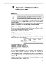
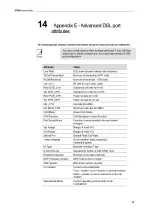
Attribute 

Value 

Detect Noise 

Enables/disables noise detection (only valid for 
Annex AHS) 

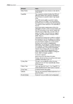
Capability 

This parameter controls whether the CPE will 
attempt to startup using alternate standards if 
the CO does not support G.Span (High Speed 
(HS)). 
The CPE has the ability to connect in either 
ADSL Annex A or G.Span. This is provided by 
the ADSL/Annex A /G.Span Auto Detect feature. 
The standard used depends on the capability of 
the CO. 
Using Auto Detect, startup at the CPE is first 
attempted in Annex A. The CO is the master and 
the CPE is the slave. If the result of handshake 
with the CO is G.Span (HS), then the CPE will 
switch to G.Span. If the CO does not support 
G.Span, then the resultant connection will be 
ADSL Annex A. 
This parameter must be set to AHS to configure 
the modem for A & HS ‘two-speed’ Auto Detect. 
For Auto Detect, all other parameters should be 
set to the Annex A profile. If UTOPIA Level 2 
framing is set (using the UtopiaInterface 
parameter), ensure that the UTOPIA address is 
set (using the PhysicalPort parameter) as there 
is no default value. If the result of handshake 
with the CO is G.Span (HS), then the CPE will 
switch to G.Span and the appropriate CPE 
parameters will be automatically re-configured 
by the DSP for G.Span operation. 
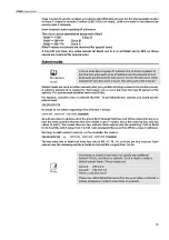
A: Annex A capable 
AHS: Annex A or High Speed capable   
Disable: the device does not send any standards 
capability information to the CO. 

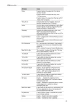
The gain due to trellis/RS coding. Its value 
ranges from 0-7 dB. 

Auto

 automatically selects 

the coding gain. 

Coding Gain 

Value can be set to Type 0 – 3 or Type3ET. To 
enable DataBoost set FramerType to Type3ET 

Framer Type 

Dying Gasp 

Enables/disables dying gasp. 

Sets the recommended default parameters for a 
given Standard. 

Defaults 

Reset Defaults 

Reset device to use default port configuration 


82


Summary of Contents for X7968r

Page 1: ...User Manual X7968r Broadband Wireless Gateway ADSL2 Bridge Router with integrated 802 11b g WLAN AP and 4 port Fast Ethernet switch Issue 1 0 16th Jan 2008...

Page 2: ...ephone line 7 Step 2 Connect the Ethernet cable 7 Step 3 Attach the power connector 7 Step 4 Configure your Ethernet PCs 7 Step 5 Install a Wireless card and connect Wireless PCs 7 Next step 7 4 Getti...

Page 3: ...g 29 Registrar 29 Internet Connection Page 30 Connections 30 ADSL Configuration 31 MAC Spoofing 32 Local Network LAN Page 33 IP Address 33 DNS Client 34 DNS Relay 34 DNS Local Host 35 DHCP server Page...

Page 4: ...SNTP Server 66 11 Appendix A Configuring the Internet Settings 67 Configuring Ethernet PCs 67 Before you begin 67 Windows Vista PCs 67 Windows XP PCs 67 Windows 2000 PCs 68 Windows Me PCs 68 Windows 9...

Page 5: ...13 Appendix D Troubleshooting 74 Troubleshooting Suggestions 74 Diagnosing Problem using IP Utilities 76 Ping 76 nslookup 76 14 Appendix E Advanced DSL port attributes 78 15 Appendix F Glossary 83 16...

Page 6: ...can deploy ADSL rapidly over existing wire infrastructure POTS or ISDN line z Compatible and interoperable with most central office site ADSL DSLAM or Multi service Access Systems z RFC 1483 Bridging...

Page 7: ...to the device using the ports labeled LAN1 to LAN4 on the rear panel Using this Document Notational conventions Acronyms are defined the first time they appear in the text and also in the glossary Fo...

Page 8: ...this document your package should arrive containing the following The device X7968r Ethernet cable Standard phone DSL line cable Power adapter User Manual CD X7968r ADSL device unit RJ 45 Cable RJ 11...

Page 9: ...ce is powered on Off device is powered off Green ADSL Green On DSL link reaches showtime which means that your device has successfully connected to your ISP s DSL network Off DSL link not in showtime...

Page 10: ...nction ON OFF switch 12V 1A Connects to the supplied power adapter Connects the device via Ethernet to your devices in LAN 1X 4X Ethernet Press and hold this button for 1 second to enable Wireless AP...

Page 11: ...se instructions provide a basic configuration that should be compatible with your home or small office network setup Refer to the subsequent chapters for additional configuration instructions Connecti...

Page 12: ...boot up your computer s and any LAN devices such as hubs or switches Step 4 Configure your Ethernet PCs You must also configure the Internet properties on your Ethernet PCs See Configuring Ethernet PC...

Page 13: ...cted to the LAN or WLAN port on the device A web browser installed on the PC The minimum browser version requirement is Internet Explorer v4 or Netscape v4 For the best display quality use latest vers...

Page 14: ...configuration It includes the sub menus Quick Setup Wireless Network Internet Connection Local Network DHCP Server VLAN Config and Port PVC Security provides filtering forwarding and setting up the v...

Page 15: ...one radio button from the selection of two or more available You cannot select more than one radio button at a time This button appears on every configuration page Click on this button once you are th...

Page 16: ...Solid green to indicate that the Wireless LAN function is operational WLAN Solid green to indicate that the device can communicate with your LAN LAN Flashing on off while trying to SYNC UP with ISP C...

Page 17: ...d password to access the device User Password admin admin DSL Port IP Address Unnumbered interface 192 168 1 1 Subnet mask 255 255 255 255 This is the temporary public IP address of the WAN port on th...

Page 18: ...like System Information equipment vendor model number chipset part number chipset version number Internet Information ADSL port downstream rate upstream rate default Gateway Primary DNS Server Second...

Page 19: ...dition to the information displayed as under Basic it also displays the DSL Firmware Version and Wireless Version Internet Connection In addition to the information displayed as under Basic it also di...

Page 20: ...Guide Wireless Settings displays the wireless settings for the modem LAN Port displays the same information as displayed under Basic Status displays the status of Routing DHCP ARP Wireless Connection...

Page 21: ...d LAN port Figure 8 Routing Table Status DHCP Table This web page shows all the PCs who request an IP address from the device Those messages show in the web page MAC address of PC assigned IP address...

Page 22: ...ice learns from the data traffic Besides it also records the interface where the device learns this information Figure 11 ARP Table Status Traffic Statistics This web page shows traffic statistics of...

Page 23: ...ayed in the drop down list For example pppoa pppoe or Rfc1483Up Enter the well known site in Internet and click Ping to check the path between the device and web site is OK or not Click on to run the...

Page 24: ...essing quick setup you should ask for the following information from your ISP z VPI VCI z Protocol PPPoA PPPoE IPoA RFC1483 Routed or Bridging z Encapsulation Type VCMUX or LLC SNAP z IP settings Dyna...

Page 25: ...ovided by the ISP Click Next Configuring the Connection Type Figure 16 Configuring the Connection Type To configure the connection type Select the Protocol by selecting the radio button for the desire...

Page 26: ...d User Name and Password Figure 18 Configuring Broadband User Name and Password To configure the broadband user name and password Enter the user name in Broadband User Name Enter the password in Passw...

Page 27: ...168 1 1 Enter the subnet mask For example enter 255 255 255 0 You have the option to set up the secondary IP address Enter the IP address and subnet mask in Secondary IP Address and Subnet Mask respe...

Page 28: ...to discard the changes Configuring the WAN IP Settings if RFC1483 Routed Figure 21 Configuring WAN IP Settings To Configure WAN IP settings select one of the following options z Obtain an IP address a...

Page 29: ...ring the WAN IP Settings if Bridging In this mode the device is a bridge and passes all raw data traffic between WAN and LAN ports There is no need for any settings The same procedure as configuring P...

Page 30: ...connection The following are the types of settings allowed Basic Settings Advanced Settings WDS Settings MAC Address Filter Registrar Basic Settings Figure 22 Wireless Network Basic Settings Global S...

Page 31: ...ide it Security Settings Select the one of security options OFF WEP 64bits WEP 128bits WPA WPA2 WPA mixed mode Select the Authentication Mode Open or Shared Select TX key index if you select the 64bit...

Page 32: ...vanced Settings Global Setting In addition to the settings provided under basic settings you can specify Fragmentation Threshold RTS Threshold NitroXM PiggyBack and WMM Security Settings The advanced...

Page 33: ...AP reset the MAC address associated with the required port to 00 00 00 00 00 00 from web page Figure 24 Wireless Network WDS Settings Global Setting Enable Disable the Wireless Distribution System WDS...

Page 34: ...Select the MAC Auth method from Disable MAC filtering feature is disabled White List allow those PCs to connect or Black List deny those PCs to connect Enter the MAC address and click Apply You can a...

Page 35: ...g functions from this page Configure internet connection Configure ADSL Specify MAC Spoofing Figure 27 Internet Connection Configuration Connections To configure the internet connection Click Add Foll...

Page 36: ...desired line modes AnnexA T1413A A2Plus ADSL2 A2 ADSL2 M2Plus ADSL2 AnnexM M2 ADSL2 AnnexM Click Apply to save the settings Click Start to take effect the settings Click Defaults to restore factory de...

Page 37: ...e Provider To specify MAC Spoofing Select either Disabled MAC Spoofing is not used or Enabled MAC Spoofing will be used with a MAC address you provide MAC Spoofing Setup Confirm page opens based on th...

Page 38: ...ess DNS Client DNS Relay DNS LAN Host Click on Local Network under Configuration from the left hand side pane The following page opens Figure 31 Local Network Configuration IP address IP Address This...

Page 39: ...igure the DNS client by specifying the IP address of DNS server Click Add Figure 32 DNS Client DNS Relay Figure 33 DNS Relay To add the fixed DNS Relay servers for getting the IP address from domain n...

Page 40: ...st name and IP address will be shown in this page you can refresh the details by clicking Refresh To create a new DNS Hostname Click Create a New DNS Hostname entry manually DNS Table page opens Enter...

Page 41: ...igure the DHCP Server Global Settings Enable disable the DHCP server by clicking Enabled Disabled The current status of the DHCP sever is changed accordingly Specify the IP Interface by selecting it f...

Page 42: ...ult lease time By default the maximum and default lease time are specified as 86400 and 43200 seconds respectively Specify the IP Address range by entering the Start of address range and End of addres...

Page 43: ...Add Fixed Host to open below page to specify a dedicated IP address for a specified PC MAC address Please make sure this IP is in the service range and does not clash an IP address already presented...

Page 44: ...hen bridge it to other interface group or route it to ADSL WAN port Figure 40 VLAN Configuration VLAN setting To click the Edit to modify the information of VLAN group and click the Delete to delete t...

Page 45: ...igure 43 VLAN Configuration Add VLAN setting 2 Port PVC Page To setup the relationship among those VLAN groups and bridge interfaces click the selection list to select the VLAN to establish a link bet...

Page 46: ...following submenus IP Filtering Domain Filtering Port Forwarding Virtual Server MAC Filtering IP Filtering Figure 45 IP Filtering Configuration IP Filter Settings To specify the IP filter settings Ena...

Page 47: ...int means the path is between the WAN port and LAN ports including WLAN port z The ext dmz means the path is between the WAN port and the specified DMZ port z The dmz int means the path is between the...

Page 48: ...ter settings Specify the rule action as Allow or Deny and click Apply Enter the filter details such as Filter Name Policy Name refer the description in IP Filtering Domain Filter enter the domain name...

Page 49: ...on a particular port to the chosen computer on your network Figure 48 Port Forwarding Configuration To configure port forwarding Click Add Add New Part Forwarding Rule page opens Figure 49 Port Forwa...

Page 50: ...arding and IP filter settings A DMZ is often used to host Web servers FTP servers etc that need to be accessible from the Internet Note Setting up a DMZ has implications on the security of your networ...

Page 51: ...n not connect to your device To setup the MAC filtering feature Select the MAC Auth method from Disable MAC filtering feature is disabled White List allow those PCs to connect or Black List deny those...

Page 52: ...nternet See Help for more information Figure 52 IGMP Proxy Configuration To enable IGMP proxy Select the Forward All to enable IGMP proxy in all interfaces Or select the connection Interface from Inte...

Page 53: ...able Figure 54 Static IP Routing Configuration Global settings Specify the destination IP address and its subnet Specify the gateway IP address or the interface LAN or WAN port where above destination...

Page 54: ...2 or both Select the Operation Mode as Active Passive or Send Only Select Enabled Click Apply Dynamic DNS The Dynamic DNS feature allows you to bind the dynamic assigned WAN IP address into a specifie...

Page 55: ...lick to select the Dynamic Service Provider Click to select the Internet Connection WAN port Enter the registered User Name and Password or Email and Key according to the requirement of Dynamic Servic...

Page 56: ...ou can configure the priority of packets through this web page By default the Classifier details are displayed Classifier Figure 58 Quality of Service Click Add Profile to create the packet classifier...

Page 57: ...VLAN ID value Prioritize packets in Layer 3 All the incoming packets will be matched against the configured values of the layer 3 fields source destination IP address mask DSCP values etc If any of t...

Page 58: ...ort applications that would not otherwise work behind the device Both UPnP Internet Gateway Device and NAT Traversal are supported Figure 61 UPnP Configuration To enable or disable the UPnP service Se...

Page 59: ...thernet Ethernet DSL A1 This web page shows the ADSL status in details If you are interesting in the parameters please contact technical support to get the description You can view two types of values...

Page 60: ...X7968r User s Guide Advanced Figure 63 View Advanced DSL Port Parameters 55...

Page 61: ...ss status in details If you are interesting in the parameters please contact technical support to get the description You can view two types of values for wireless port statistics These are Basic Adva...

Page 62: ...X7968r User s Guide Advanced Figure 65 View Advanced Wireless Port Parameters 57...

Page 63: ...interesting in the parameters please contact technical support to get the description You can view two types of values for raw Ethernet port statistics These are Basic Advanced Basic Figure 66 View B...

Page 64: ...re interesting in the parameters please contact technical support to get the description You can view two types of values for Ethernet port statistics These are Basic Advanced Basic Figure 68 View Bas...

Page 65: ...the current version of the firmware and lets you upgrade to the latest version Figure 70 Upgrading Firmware To upgrade the firmware you have two options Automatically check for the updates Click Check...

Page 66: ...backup configuration file Click Backup Please be noted that only configuration saved to flash will be backed up A message window opens prompting you to save the file Click Save Specify the path where...

Page 67: ...oration Click restart to save new configuration Reboot This submenu lets you reboot the modem You can reboot form the following configurations Last Configuration Factory Configuration Figure 72 Reboot...

Page 68: ...Figure 74 Remote Access Configuration To enable the remote access Specify the method by which you wish to access the router remotely by selecting it The following are the methods available for remote...

Page 69: ...ord Figure 75 Administration Password Configuration To change the password Select the user name in User name Enter the New Password Confirm the password by retyping it in Confirm New password Click Ap...

Page 70: ...Clock Manually and specify the time in System Clock in YYYY MM DD HH MM SS format Select the Time Zone from the drop down list Specify whether the day light savings applies by selecting Day Light Savi...

Page 71: ...e 77 SNTP Server Configuration To configure the SNTP client Select one of the options Host Name or IP Address Enter the required information and click Add You could click the Delete icon to remove the...

Page 72: ...ons If you want to allow Wireless PCs to access your device follow the instructions in Configuring Wireless PCs below Windows Vista PCs In the Windows task bar click the Start button and then click Co...

Page 73: ...lect Protocol and then click Add Select Internet Protocol TCP IP in the Network Protocols list and then click OK You may be prompted to install files from your Windows 2000 installation CD or other me...

Page 74: ...with a list of currently installed network components If the list includes TCP IP and then the protocol has already been enabled Skip to step 9 If TCP IP does not display as an installed component cl...

Page 75: ...nformation to your PCs If you are a typical user you will not need to assign static Internet information to your LAN PCs because your ISP automatically assigns this information for you In some cases h...

Page 76: ...figuring PC access to your Wireless device Before you start configuring your Wireless PC you must ensure that you have A Wireless access card for each of the PCs Corresponding wireless access card dri...

Page 77: ...t or intranet Host ID Identifies a particular computer or device on the network The first part of every IP address contains the network ID and the rest of the address contains the host ID The length o...

Page 78: ...dentifies these host ID bits For example consider a class C network 192 168 1 To split this into two subnets you would use the subnet mask 255 255 255 128 It s easier to see what s happening if we wri...

Page 79: ...work 10BaseTx should use cables labeled CAT 5 A 10Mbit sec network may tolerate lower quality cables Internet Access My PC cannot access the Internet Run a health check on your device Use the ping uti...

Page 80: ...s any custom settings and returns all settings to their default values I cannot access the web pages from my browser Use the ping utility discussed in the following section to check whether the PC can...

Page 81: ...also test whether access to the Internet is working by typing an external address such as that for www yahoo com 216 115 108 243 If you do not know the IP address of a particular Internet location yo...

Page 82: ...esses associated with an Internet name This is common for web sites that receive heavy traffic they use multiple redundant servers to carry the same information To exit from the nslookup utility type...

Page 83: ...ll rate for rt vbr Vbr PCR_CPS Peak cell rate for nrt vbr Ubr_CPS Cell rate for UBR Ubr MCR_CPS Minimum Cell rate for UBR CACMode Gives CAC Mode CACFunction Call Admission control function Function to...

Page 84: ...Country Code Number of severely errored frame defects received by the device Local SEF Number of loss of signal defects received by the device Local End LOS Local SNRMargin The local Signal to Noise R...

Page 85: ...te Fast Channel HEC Number of ATM Cell Header errors corrected by the device on the fast channel Remote Fast Channel NCD Number of no cell delineation received by the device on the fast channel Remote...

Page 86: ...en 1 and 15 Max Bits Per Bin A value that indicates the lowest bin number allowed for transmit signal Tx Start Bin A value that indicates the highest bin number allowed for transmit signal Tx End Bin...

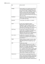
Page 87: ...or A HS two speed Auto Detect For Auto Detect all other parameters should be set to the Annex A profile If UTOPIA Level 2 framing is set using the UtopiaInterface parameter ensure that the UTOPIA addr...

Page 88: ...ownload much more data from the Internet than they upload Analog An analog signal is a signal that has had its frequency modified in some way such as by amplifying its strength or varying its frequenc...

Page 89: ...he DHCP server that assigns the addresses Each of the device s interfaces can be configured as a DHCP relay See DHCP DHCP server Dynamic Host Configuration Protocol server A DHCP server is a computer...

Page 90: ...data rates are often expressed in Gbps Host A device usually a computer connected to a network HTTP Hyper Text Transfer Protocol HTTP is the main protocol used to transfer data from web sites so that...

Page 91: ...small geographic area such as a home or small office LED Light Emitting Diode An electronic light emitting device The indicator lights on the front of the device are LEDs MAC address Media Access Cont...

Page 92: ...estination address Ping Packet Internet or Inter Network Groper A program used to verify whether the host associated with an IP address is online It can also be used to reveal the IP address for a giv...

Page 93: ...s remain physically connected to the rest of the parent network but they are treated as though they were on a separate network See network mask Subnet mask A mask that defines a subnet See network mas...

Page 94: ...r grade called Category 3 CAT 3 is used for 10BASE T networks and an even higher grade called Category 5 CAT 5 is used for 100BASE T networks See 10BASE T 100BASE T Ethernet Unnumbered interfaces An u...

Page 95: ...to blocks of either 64 bits length or 128 bits length The encrypted data can only be sent and received by users with access to a private network key Each PC on your wireless network must be manually c...

Page 96: ...cation The mode of WPA supported on your device is called Pre Shared Key PSK which allows you to manually enter a type of key called a pass phrase WWW World Wide Web Also called the Web Collective ter...

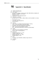
Page 97: ...tion Loops One pair wire Connector RJ 11 Indicators LAN Green LED indicates LAN data transmitting receiving WLAN Green LED indicates wireless AP enabled Encendido Green LED indicates power and operati...

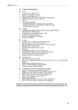
Page 98: ...1483 Routed NAT PAT with extensive ALG support DNS relay IP multicasting IGMP v1 v2 and IGMP proxy Multihoming IP aliasing and unnumbered IP interfaces Virtual interface and secondary IP addresses Sup...

Page 99: ...gainst harmful interference in a residential installation This equipment generates uses and can radiate radio frequency energy and if not installed and used in accordance with the instructions may cau...

Page 100: ...o you will be notified in advance to give you an opportunity to maintain uninterrupted telephone service If you experience trouble with this telephone equipment Please contact the following address an...

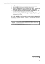
Page 101: ...e risk of electric shock from lightening 9 Do not use the telephone to report a gas leak in the vicinity of the leak 9 Use only the power cord batteries indicated in this manual Do not dispose of batt...

Reviews: