INSTALLATION INSTRUCTIONS
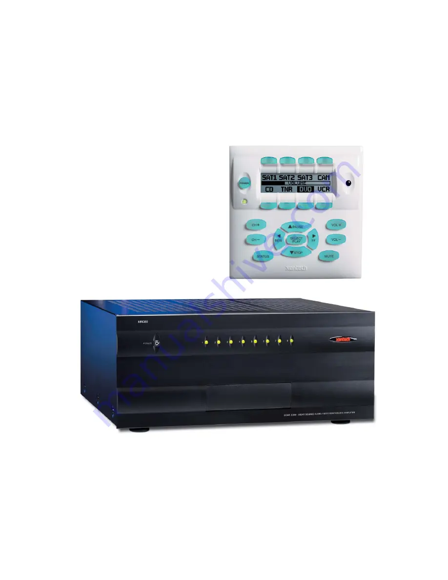
MODEL MRC88m
MODEL MRAUDIO8x8m
EIGHT ZONE – EIGHT SOURCE
AUDIO & AUDIO/VIDEO CONTROLLER/AMPLIFIER SYSTEMS
Page 1: ...INSTALLATION INSTRUCTIONS MODEL MRC88m MODEL MRAUDIO8x8m EIGHT ZONE EIGHT SOURCE AUDIO AUDIO VIDEO CONTROLLER AMPLIFIER SYSTEMS...
Page 2: ...d by the manufacturer 8 Ventilation The appliance should be situated so that its location or position does not interfere with its proper ventilation For example the appliance should not be situated on...
Page 3: ...TING THE MRC88M CONTROLLER AMPLIFIER 25 SOURCE RELATED CONNECTIONS 25 Source Component Connections 25 Zone Audio Inputs 26 IR Control Connections 26 Sense Input Connections 26 ZONE RELATED WIRING CONN...
Page 4: ...ch com 43 Remote Central com Importing CCF Files and Discrete IR Commands 43 ENTERING RS232 COMMANDS CREATING RS232 COMMAND PALETTE FILES 45 ENTERING RS232 COMMAND STRINGS 45 Using the RS232 Palette E...
Page 5: ...5 ADVANCED EXPANDED PROGRAMMING 62 CONTROLLER OPTIONS PROGRAMMING 62 ZONE AUDIO INPUT 62 IR ROUTING 63 BACK LIGHT CONTROL 63 MODE OF OPERATION 63 Whole House Mode 63 Priority Lockout Mode 63 EXPANDED...
Page 6: ...ACHING A HAND HELD REMOTE TO OPERATE THE MRC88M SYSTEM 80 TEACHING A HAND HELD REMOTE USING AN RC68 HAND HELD PROGRAMMER 80 TEACHING A HAND HELD REMOTE DIRECTLY FROM DRAGON DROP IR 80 MAKING FINE ADJU...
Page 7: ...Model MRC88m MRAUDIO8x8m Page 7 2009 Xantech Corporation...
Page 8: ...serial port on your PC Part No 05913410 One male DB15 to male DB15 cable with null modem for linking two MRC88m Controllers Part No 05913555 CD ROM Disc contains the MRC88m Dragon Drop IR software Par...
Page 9: ...rogramming by zone etc The Expanded mode allows programming of systems with more than Eight zones using linked MRC88m Controllers Each section of this manual will indicate which sections apply to the...
Page 10: ...st standard source components via IR and or RS232 commands Two Control Amps can be linked to create systems with up to Sixteen zones POWER CH CH STATUS SELECT PLAY STOP PAUSE FF REW VOL VOL MUTE POWER...
Page 11: ...deo applies to MRC88m only Power Management Keeps all components Power States in sync with Zone Power Status All Eight video source inputs have built in NTSC PAL sync sensing Applies to MRC88m Only Al...
Page 12: ...rogrammable dual functionality tiered push and hold on most buttons Backlit LCD and buttons w rear panel brightness adjustment Variable backlight timeout Bi colored Status LED for power and status Bro...
Page 13: ...itch Turns AC power On Off to the entire unit 4 Power and Status LED Indicators Eight indicators one for each Zone provide the following status information System Status Power Up Mode a Slow Orange Bl...
Page 14: ...naltered factory defaults after main power shut down or after any power interruptions 7 IR Learning Eye The IR Eye on the MRC88m Controller front panel allows teaching IR Codes to Dragon Drop IR via t...
Page 15: ...r modulator Applies to MRC88m only 19 Status Out 8 Provides a control output of 12 VDC that turns on and off with the zone to drive voltage sensing relay modules and AC strips 20 Control Out 8 Mono 3...
Page 16: ...s ADVANCED only See Section 5 Controller Options Programming 27 IR Emitter Common 3 5mm Mono Mini Phone Jacks Single Common IR Output that can be used to control devices such as Multi Zone Audio Serve...
Page 17: ...ce components and the MRC88m system A Programmable Learning Remote such as the Xantech URC2 is recommended for integrating the IR commands of the MRC88m and source components into a single controller...
Page 18: ...pressed Pressing of the Source Button will reverse the source icon on the LCD Display and sends IR commands programmed to the button if any to the corresponding source and common emitter outputs as we...
Page 19: ...er 20 IR Sensitivity Adjustment Carefully adjust for background light level to prevent false triggering of the IR circuits Slowly turn counter clockwise to reduce sensitivity 21 LCD Backlight Adjustme...
Page 20: ...nputs 1 Audio Video RCA Harness Capable of Audio Left Right and Video 1 Pair of speakers with Speaker Cable properly terminated into a 4 conductor WECO Plug Will be used to test Speaker outputs 1 TV o...
Page 21: ...pad is transmitted along the CAT5 cable Incorrect wiring on this cable can destroy the MRC Keypad Please test the cable connections using a proper CAT5 cable tester or using a Multimeter to check Pin...
Page 22: ...C88m is designed for mounting on flat horizontal surfaces When mounting into a 19 rack use a proper rack shelf or drawer i e Middle Atlantic or equivalent 8 Do not remove chassis feet They are necessa...
Page 23: ...ine of the template being sure that your cut is on the outline Any cut outside of the outline by more than may not be covered by the MRC88m Keypad 1 2 Figure 8 Installing the MRC88m Keypad mounting br...
Page 24: ...stallation optional a Position Back Box so inner rectangle is in a horizontal position as shown in Figure 8B b Affix MRCBOX to Wall Stud at desired height with front of box flush with front of stud or...
Page 25: ...for a typical MRC88m system layout and interconnections SOURCE RELATED CONNECTIONS The following relates to all source related connections to the MRC88m Controller Unit A V In Out IR Control Sense Inp...
Page 26: ...CONNECTIONS BASIC ADVANCED The sense input connection will typically be used to sense the power state of a source component using the Xantech CSM1 Current Sense Module optional Plug the 3 5mm mini pl...
Page 27: ...ep 6 Since the connectors are removable you may unplug them for ease of lead assembly 4 As a rule of thumb use 18 gauge speaker wire for speaker runs up to 30 9m 16 gauge up to 70 21m and 14 gauge up...
Page 28: ...wiring on this cable can destroy the MRC Keypad Be sure to test cable for proper connections before making connections VIDEO CONNECTIONS MRC88M ONLY BASIC ADVANCED EXPANDED Composite Video 1 When runn...
Page 29: ...cables connect the Preamp Out Left L and Right R connectors Figure 3 25 to the desired external amplifiers Audio Left and Right Input connectors CO1 AND CO2 ZONES 7 8 BASIC ADVANCED EXPANDED Zones 7...
Page 30: ...e Address jumpers on the rear of the keypad Figure 5 17 according to Table 1 below Keypad Address Setting Application JP1 JP2 First or Single Keypad in Zone Primary Keypad connected directly to MRC88m...
Page 31: ...ms greater than 8 Zones two MRC88m Controller Amplifiers can be linked together for systems up to 16 Zones Zone expansion is only available in Advanced programming configurations LINKING TWO MRC88M CO...
Page 32: ...STOP PAUSE FF REW VOL VOL MUTE POWER CH CH STATUS SELECT PLAY STOP PAUSE FF REW VOL VOL MUTE D 250 feet max 76 m MRC44 Connecting Block PWR V G S IR RCVR 780 80 CFL DIRECT SUNLIGHT FRIENDLY IR RECEIV...
Page 33: ...SIC ADVANCED EXPANDED SPEAKER PHASING TO OBTAIN STABLE IMAGING AND FULL BASS RESPONSE IT IS IMPERATIVE THAT STEREO SPEAKERS BE CONNECTED IN PHASE WITH EACH OTHER YOU CAN VERIFY THIS AS FOLLOWS 1 If th...
Page 34: ...O OUT ZONE 4 AUDIO OUT ZONE 5 AUDIO OUT ZONE 6 A V Source 1 To MRC88 Controller Amplifier IR Out s A V Source 8 To MRC88 Controller Amplifier IR Out s AUDIO OUT ZONE 7 AUDIO OUT ZONE 8 VIDEO OUT ZONE...
Page 35: ...nications between the keypad and the controller This means the system is programmed as a whole which saves programming time and ease of maintenance Keypads can be interchanged or replaced without any...
Page 36: ...________ IR File Name _____________ IR Library Palette Zone Audio Source 3 ______________ IR File Name _____________ IR Library Palette Zone Audio Source 7 ______________ IR File Name _____________ IR...
Page 37: ...as been set for auto run a Xantech Welcome Menu will appear If not access your CD ROM with Windows Explorer and double click the file setup exe 2 On the Welcome menu click NEXT 3 Follow the on screen...
Page 38: ...er state of the unit 2 There is a communication error between the PC and the MRC88m Controller Amplifier Please verify the DB9 or USB cable is properly connected to the unit and there are no Com Port...
Page 39: ...ned in palettes please proceed to the section entitled PUTTING CODES TO WORK BUILT IN IR CODE LIBRARY BASIC ADVANCED EXPANDED The DragMRC software has a built in IR Code Library This is basically a la...
Page 40: ...box labeled IR Library You will need to remember the location of all commands for use in the following section Figure 16 Built In Mfg s IR Command Library LEARNING IR COMMANDS BASIC ADVANCED EXPANDED...
Page 41: ...n in Palette Editor Figure 18 Source COMPONENT selection in Palette Editor RECORDING TOGGLE COMMAND FUNCTIONS Some IR command formats e g RC5 and RC6 types include a toggle or key release bit in the c...
Page 42: ...c NOTE Only functions with an asterisk will execute 7 If a component does not respond to a command re learn and re test the IR command until the component responds 8 Repeat steps 1 thru 6 for all comm...
Page 43: ...ctions required for the new component 5 Press ESC on keyboard to save and exit 6 New Brands Components and Functions can now be selected and programmed in Palette Editor GETTING SOURCE COMMANDS FROM T...
Page 44: ...he file import to the Brand and bci files in DragMRC 17 At this point or at any later date you can choose additional component types from the CCF file e g DVD etc if listed by using the CCF Importer a...
Page 45: ...f FUNCTIONS for that type of component will appear as shown in Figure 21 Review the list of Functions on the left hand side and compare to the source remote If your function is not displayed or not na...
Page 46: ...roper communication settings 4 Click on the command string to be tested on the left hand side of the RS232 Palette Editor Note Only commands with the icon will be able to be tested 5 The Device or Com...
Page 47: ...le of issuing RS232 commands Therefore the procedure of learning and testing these commands and creating the Palette file for an individual source component only needs to be done once This file can no...
Page 48: ...the sections to follow you will be setting up the Keypads for use in controlling the system This will consist of setting up the Source Icons placing IR or RS232 commands onto the Virtual Keypad and se...
Page 49: ...icons 7 Select the ZONES tab in the Project Window 8 Right click on the Source button to be labeled 9 From the pop up menu Select LOAD ICON A list of icon bitmaps will appear including new icons 10 S...
Page 50: ...dow boxes can be moved and sized except the virtual keypads for ease of use If you click on a Palette file in the list and you do not see it on the screen move some of the currently opened windows to...
Page 51: ...SEQUENCES MACROS All programmable buttons on the MRC88m Keypad can be programmed to send IR sequences of up to 40 commands all buttons except for Volume UP DOWN and STATUS 1 Click the button to be pr...
Page 52: ...the button is pressed and held for longer than 1 second NOTE Tier 2 commands placed under the POWER button will require the button to be held for 3 Seconds before it will execute the Tier 2 command T...
Page 53: ...l or opening closing shutters in that zone This type of function would need to be accessible regardless of which source is currently selected in that zone PUNCH ALL SYSTEM LEVEL ADVANCED EXPANDED Sele...
Page 54: ...itter port on the rear of the Keypad if enabled regardless of which zones keypad issued the command i e if Zone 2 is selected from the pop up menu pressing the associated button on Zone 1 s keypad wil...
Page 55: ...r surges or other miss happenings The MRC88m Controller features two sensing methods One is Video Sensing Available on MRC88m Only All eight source video inputs are set to detect a video input signal...
Page 56: ...SENSE SETUP tab in the MRC88m Systems window 2 Select POWER MANAGEMENT in the selection window See Figure 29 3 Select the SOURCE to program be sure to have the components IR Palette open with the pro...
Page 57: ...er Management NOTE If a Video or Sense Input is being used in Power Management for a particular source it will not be available for Sense Trigger and the corresponding button will be grayed out in the...
Page 58: ...e switches and relays need to stabilize The factory default of 2 should be tried first For a faster switch try the 1 setting For slower switches change as needed to allow the controller to sense the s...
Page 59: ...n be given a name i e Living Room Bedroom etc to more easily plan and program the keypads and zones in a MRC88m system 1 To change the name of a zone click the OPTIONS button on the bottom of the Virt...
Page 60: ...ne to be Variable and follow the Volume setting for the entire Zone track 1 1 with default MRC88m Volume controls on Keypad or RC68 commands via remote or to be a Fixed output level to be controlled o...
Page 61: ...w be transferred to the MRC88m if it is being set up in the Basic mode For Advanced and Expanded systems continue to next section See page 77 Transferring a Project for instructions NOTE For Advanced...
Page 62: ...UDIO INPUT Factory Default DISABLED Select ENABLE to utilize the Zone Audio Inputs on the rear of the MRC88m Controller Amplifier Figure 3 24 Use this feature to interface Zone Specific audio componen...
Page 63: ...will never turn on This is useful in rooms that are always brightly lit 3 Click TIMED and use the Timed Back light Control Pulldown Menu to set backlight duration from 1 10 seconds MODE OF OPERATION F...
Page 64: ...ing to prevent the MRC88m system from misinterpreting erroneous data NOTE To control the MRC88m System from the RS232 port please see Section 5 RS232 Input Translator and Section 9 Appendix RS232 Cont...
Page 65: ...Source 1 Select PRIORITY LOCKOUT MODE The Monitor Lockout boxes will be activated 2 Click the ADMINISTRATOR box for any zone that is to have Dynamic Monitor Lockout ability 3 After the project has bee...
Page 66: ...d zones POWER and SOURCE SLECTION buttons to control the zones from any linked keypad There are two forms of Linking STATIC linking and DYNAMIC linking Figure 36 MRC88m System Window Zone Linking Tab...
Page 67: ...inking DYNAMIC ZONE LINK MODE Factory default DISABLED This mode allows zone linking on the fly There may be times when it may be desirable to link multiple zones on a temporary basis i e Linking the...
Page 68: ...of IR controlled devices This can give the ability for a central PC or other RS232 device to control not only the MRC88m system itself but also any IR controlled device connected to any of the MRC88m...
Page 69: ...ar in the Command List 4 Repeat for all commands to be associated to this Command String A maximum of 40 Commands may be placed under each string 5 Repeat steps 1 thru 4 for all desired ASCII Strings...
Page 70: ...opriate emitter output AND THE zone Emitter Outputs if desired as well as the common IR output for control of other devices and systems Any Internal Amplifier Commands placed in the Macro will be proc...
Page 71: ...As noted earlier each command can be edited and directed to a specific Zone or Source emitter output port By right clicking on the desired command the command may be directed to a specific emitter out...
Page 72: ...ypad it is necessary to use these special internal amplifier commands Figure 41 Using Internal Amplifier Commands 1 In the MRC88m System Window Menu click on Palette and select MRC Amplifier Command G...
Page 73: ...16 TrebLevel 14dB 14dB Zone Treble Step Up Command Increase Treble Setting Zone 1 8 9 16 N A Zone Treble Step Down Command Decrease Treble Setting Zone 1 8 9 16 N A Zone Bass Level Command Set Bass to...
Page 74: ...these buttons to program the Zones Virtual Keypad PROGRAMMING THE SYSTEM Refer to Section 4 and follow all instructions for EXPANDED mode 1 Place commands from Palettes under any button on the virtual...
Page 75: ...32 ports are active as system control inputs 2 Any RS232 Commands placed on any keypad will be executed out of the PRIMARY Controllers rear RS232 Connector ONLY regardless of which zone is issuing the...
Page 76: ...ntroller Amplifier Sources 1 through 8 From Source Component 1 From Source Component 8 From A V loopthroughs on Primary Controller Sources 1 through 8 To IR Emitters at A V Equipment Expansion Cable f...
Page 77: ...and set the PROTECT switch to the ON position 8 MRC88m System should now be fully functional EXPANDED 1 Connect PC to the COM port or USB port on the PRIMARY MRC88m Controller 2 Set the PROTECT switc...
Page 78: ...on the main hard drive and drop them into the Projects folder in the backup directory To COPY the files to a floppy disk right click on the selected files and choose 3 5 Floppy Drive letter under the...
Page 79: ...UPGRADE WARM firmware upgrades can be conducted without having to re transfer your project to the controller It is a way of keeping your unit up to date to take advantage of new features 1 Start Drago...
Page 80: ...e On g Optional Commands can be EQ Treble and Bass commands and Balance adjustment commands TEACHING A HAND HELD REMOTE DIRECTLY FROM DRAGON DROP IR ADVANCED EXPANDED If an RC68 is not easily accessib...
Page 81: ...at the IR sensor on the MRC88m Keypad IR sensor enabled and press the TRIM button button F8 This activates the TRIM mode NOTE Trim mode allows 10 seconds after each button press for the next command t...
Page 82: ...o on power on NOTE The MRC88m remembers the last volume setting on a power down and returns to that level when the Zone is powered back up The ON VOL feature will ensure that if the volume was turned...
Page 83: ...OFF and Power Management is enabled all of the Source Components will also be powered OFF SOURCE SLECTION AND CONTROL To select Sources via the Keypad press the corresponding source button located abo...
Page 84: ...audio video output of a source from being viewed in any of the other zones DYNAMIC MONITOR LOCKOUT should be engaged from the Zone that WILL be accessing the source This is ideal to prevent a source c...
Page 85: ...d status LED s will show busy rapid amber flash for 10 seconds after the last button press then time out and return to normal use mode LED green LCD normal display The small L will no longer appear Th...
Page 86: ...Primary units RS232 port TYPES OF COMMANDS There are two types of information that can be sent to the MRC88m Controller COMMANDS and QUERIES COMMANDS are ASCII strings used to set a specific parameter...
Page 87: ...begin with an and for data queries the string must begin with a All strings must end with a This way it can determine the beginning and end of the string for processing When a proper command is sent a...
Page 88: ...PT All Zones Off AO Input Source Select z SS s To set Zone 1 to Source Input 5 1SS5 Volume z VO v Volume Increment z VI Volume Decrement z VD Mute z MU 0 1 To mute Zone 3 3MU1 To unmute Zone 4 4MU0 Mu...
Page 89: ...1TR7 Zone 1 currently has a treble value of 7 flat Bass z BS z BS bt 1BS7 Zone 1 currently has a bass value of 7 flat Balance z BA z BA t 2BA31 Zone 2 currently has a balance value of 31 even Where z...
Page 90: ...37 1 25 36 2 50 35 3 75 34 5 00 33 6 25 32 7 50 31 8 75 30 10 00 29 11 25 28 12 50 27 13 75 26 15 00 25 16 25 24 17 50 23 18 75 22 20 00 21 21 25 20 22 50 19 23 75 18 25 00 17 27 50 16 30 00 15 32 50...
Page 91: ...11 CH 12 CH 13 POWER 14 NOT AVAILABLE 15 MUTE 16 PAUSE 17 STOP 18 FF 19 REW 20 SELECT PLAY 21 NOT AVAILABLE 22 NOT AVAILABLE 23 Tier 2 Source Select 1 24 Tier 2 Source Select 2 25 Tier 2 Source Select...
Page 92: ...Page 92 Model MRC88m MRAUDIO8x8m 2009 Xantech Corporation BASS TREBLE LEVEL MRC88m SETTING LEVEL in dB 14 14 13 12 12 10 11 8 10 6 9 4 8 2 7 0 6 2 5 4 4 6 3 8 2 10 1 12 0 14...
Page 93: ...93 2009 Xantech Corporation BALANCE LEVEL 63 steps MRC88m Setting Left Speaker Attenuation in dB Right Speaker Attenuation in dB 0 0 Mute 1 0 37 5 2 0 36 25 29 0 2 5 30 0 1 25 31 0 0 32 0 0 33 1 25 0...
Page 94: ...it from the associated palette f Place the corrected command in the palette using the Add function g Close the Palette Editor and open the palette h Click the button on the virtual keypad that has th...
Page 95: ...are learnable however when down converted by Xantech products such as the 291P PMS12 291 455 MS455 etc Refer to the Xantech Product Catalog and contact Technical Support for details Be sure you have...
Page 96: ...dows with the MRC88m connect to the PC After transferring commands to the MRC88m it works fine except at certain times the MRC88m refuses to output any commands at all IR noise may be on the IR bus li...
Page 97: ...s controlling an External Device via the MRC88m rear Com Port 1 Check the cabling between the controlling unit and the MRC88m 2 Verify RS232 Port settings are set properly for both devices i e Baud Ra...
Page 98: ...R Source 1 2 Tx 2 IR Source 2 3 Rx 3 IR Source 3 4 DSR 4 IR Source 4 5 GND 5 IR Source 5 6 DTR 6 IR Source 6 7 NC 7 IR Source 7 8 NC 8 IR Source 8 9 NC 9 NC 10 IR Common 11 Tx Out 12 Common 13 Rx In 1...
Page 99: ...Sensor IR Modulation Frequency Bandwidth 30 Hz to 100 kHz Nominal Reception Range 30 feet Nominal Reception Angle 40 degrees off axis General RC68 Code Group Number A8 Control Output 12 V 50 mA Status...
Page 100: ...Page 100 Model MRC88m MRAUDIO8x8m 2009 Xantech Corporation...
Page 101: ...Model MRC88m MRAUDIO8x8m Page 101 2009 Xantech Corporation...
Page 102: ...Page 102 Model MRC88m MRAUDIO8x8m 2009 Xantech Corporation XANTECH CORPORATION 13100 Telfair Avenue Sylmar CA 91342 phone 818 362 0353 fax 818 362 9506 www xantech com Part No 08901180 Rev E 08 10 09...