

Start Here
3
4
5
6
7
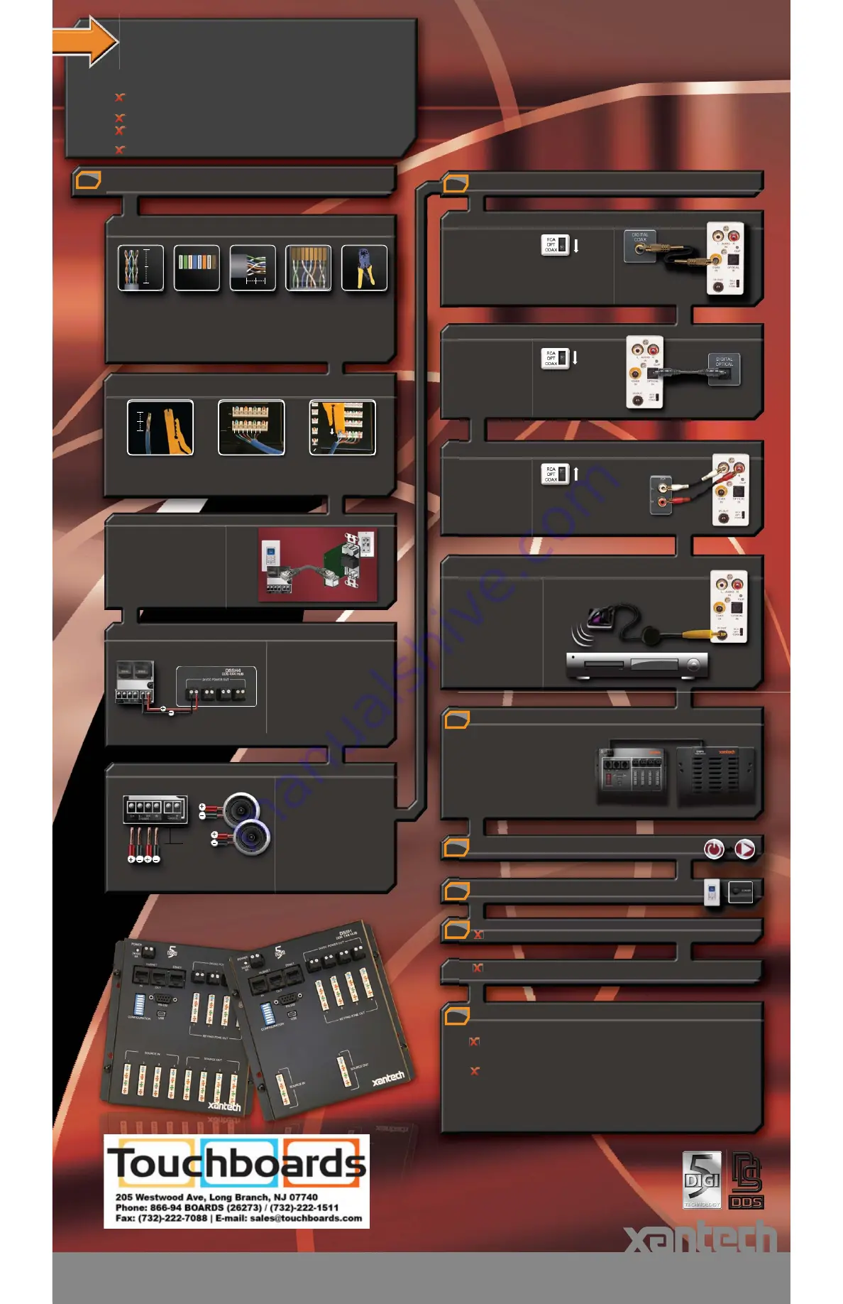
Connect Audio Sources To D5SH – Options
Connect D5KP Keypad to D5SH Digital Distribution Hub.
Connect D5IP Input Plate to D5SH Digital Distribution Hub.
Turn On and Start All Connected Audio Sources
Turn On All Zone Keypads (Front of D5KP – "PWR" button)
Verify Audio for Each Source
Ramp volume up to the halfway point.
Starting with Source 1, select each source and verify that audio is present through the
room speakers.
If Necessary, Adjust Source Input Gain for Analog Source Inputs
Connect Power to the Digital Distribution System
A
– Digital Coax Setup
A
– Digital Coax Setup
B
– Digital Optical Setup
C
– Analog Setup
There are two reasons that the Source Input Gain DIP switches may need to be adjusted:
The volume levels of analog source inputs are high adjust the
DIP switches up or down to boost or cut input level
A- Connect AC power cord to the D5PS
Power Supply.
B- Connect the 24 VDC power cord from
the D5PS Power Supply to the D5SH
Digital Distribution Hub.
If there is noticeable distortion (clipping) coming from analog
source, even at low volume levels - check the clip indicators on
the front of the D5IP to verify clipping and flip the DIP switch to
the down (default) position
1
For audio sources with
a digital coax output,
connect the digital coax
output to the D5IP
Digital Coax Input with
a coaxial cable.
D5IP
Front
D5IP
Front
D5IP
Front
Digital
Coax
Cable
D
– Connect & Mount IR Emitters
Connect the 3.5 mm plug of
each IR emitter into the
“IR OUT” on the D5IP.
Place the IR Emitter head
onto the source equipment
connected to the respective
D5IP.
D5IP
Front
IR Emitter
CD
Audio Source
Coax Output
Set switch
to the "COAX"
position.
For audio sources with
a digital optical output,
connect the digital optical
output to the D5IP
Digital Optical Input
with a optical cable.
Digital
Optical
Cable
Audio Source
Digital Optical
Output
Set switch
to the "OPT"
position.
For audio sources with
an analog audio output,
connect the analog
output to the D5IP
RCA Input with a stereo
RCA cable.
Stereo RCA
Patch Cable
Audio Source
Analog Output
Set switch
to the "RCA"
position.
D5PS
D5SH
Determine the best location for the D5SH and all audio source equipment
(CD player, radio tuner, iPod®, etc.)
Run a Cat5 wire from each room (Zone) Keypad location to the D5SH
Run speaker wiring (16 gauge is recommended) from each Keypad location to
the corresponding speakers located in each room
Be sure to label all wires for easy identification
Connect D5KP Keypads
NOTE:
For maximum audio performance over
long wiring distances (over 150ft) an
additional 16 gauge, 2 conductor wire
is recommend for extra power.
For all zones requiring extra power,
connect the "24 VDC POWER OUT” of
the D5SH to the “POWER IN” of the D5KP.
For more information, consult the D5SH
manual.
D5KP Rear
D5SH
Connect Speakers To D5KP Keypads
Strip approximately 1/4" of insulation
from both ends of all speaker wiring.
Twist the exposed end of the wire to
ensure no loose strands remain.
Connect the positive speaker wire to
the positive input of the speaker and
negative speaker wire to each negative
input of each speaker.
1/4"
Speaker Connector
16AWG
Speaker Wire
To Speakers
D5KP Rear
Digital Distribution System
Quick Start Guide
Digital Distribution System
Quick Start Guide
A
– Terminate RJ-45 Plugs and Connect to “SYSTEM PORT” (D5KP side)
Using a Cat-5
cable stripper,
remove about
1 - 1/2" of the
jacket as shown
above.
1 1/2"
1/2"
1 2 3 4 5 6 7 8
1 2 3 4 5 6 7 8
Green/White
Orang
e/White
Blue/White
Bro
wn/White
Green
Blue
O
rang
e
Bro
w
n
Untwist the twist-
ed pair wires and
arrange them in
the order shown
above.
Press all wires
flat between your
thumb and index
fingers and cut
the wires so they
are 1/2" long as
shown above.
Insert the ar-
ranged wires into
the RJ-45 plug
as shown above.
The locking tab
is facing down in
this view.
Finally, crimp the
connector using
a standard RJ-45
crimping tool.
If a local audio source is desired,
such as an iPod® a D5IP Source
Input Wall Plate is required.
Terminate RJ-45 plugs on each end
of the C at5 as shown in step 1A
.
Connect the "local port" of the D5KP
to the RJ-45 input of the D5IP.
Connect the audio source to the
D5IP.
For more information consult your
D5IP manual.
LOCAL PO RT
D5KP Rear
D5IP
Sideview
Cat5
13100 Telfair Ave. Sylmar CA 91342 I 818.362.0353 I xantech.com
iPod is a registered trademark of Apple Computer, Inc. All other marks are registered trademarks and trademarks of
Xantech Corporation. All rights reserved.
This document is copyright protected. No part of this manual may be copied or reproduced in any form without prior
written consent from Xantech Corporation. Xantech Corporation shall not be liable for operational, technical, or editorial
errors/omissions made in this document.
Instructions, Quick Start, D5SH, D5SH4 © 2008 Xantech Corporation Document # 08905182 REV. A
24VDC
B
- Terminate 110 Punch-down from D5KP.
Using a Cat-5
cable stripper,
remove about
2-3” of the jacket.
Align the wires
to the color coded
110-Punch-down.
Blue/ White is the first
wire to be installed.
Terminate the wires
by using a Punch-
down tool.
Cat5
Cable
Stipper
2"
This setup guide is intended for the D5SH and D5SH4 wall-mount Digital Distribution
System. The D5SH is a single source distribution hub, the D5SH4 is a four source
distribution hub. Each D5SH or D5SH4 requires one D5PS power supply. For ease of
reading, the distribution hub will be referred to as the model D5SH.
2
Terminate RJ-45 Plugs and Connect to D5IP
Terminate 110 Punch-down from D5IP.