background image

www.xa.com/en

17

Description of Status Indicator/Buzzer

There are 3 indicator LEDs on the Automatic Liquid Refiller, each indicating a status as follows:

RED LIGHT ON

GREEN LIGHT ON

Charging

OFF

YELLOW LIGHT ON

Charging completed

RED LIGHT FLASHES

RED LIGHT ON

RED LIGHT FLASH

LED Display

Description

Battery Level

Charge

LED Display

Battery

50%-100%
25% -50%
5%-25%
Power level lower than 5%. Please recharge 

in a timely fashion.

Charging circuit failure or battery 

overdischarge

The refiller detects that the container has been accurately 

placed.

The refiller fails to detect the placement of the container 

when it starts operation.

The refiller fails to connect to the container via Bluetooth 

when it starts operation.


The float of the container is stuck or the inlet tube or the 

refiller is blocked.

The refiller detects irregular rotational speed.

The refiller has completed the operation.

The filler detects low battery level. The operation is 

suspended. All indicators flash eight times and the buzzer 

beeps eight times before refiller turns off automatically.

Charge the refiller immediately.

RED LIGHT 

ON

RED LIGHT 

ON

RED LIGHT 

ON

RED LIGHT 

ON

LED Display

Description

Warning/Beep

Once

Twice

Three 

 times

Four 

times

Five 

times

Six times

Eight 

times

Fault

THREE LIGHT FLASHING (Green)

TWO LIGHT SLOW FLASH (RED)

GPS MODE

SAFE MODE

Auto

Check the UAV Status

Flight Status Indicator

ONE RED + ONE GREEN LIGHT FLASH

TWO LIGHT FLASHING (Green)

SOLID RED

QUICK FLASH PURPLE

QUICK FLASH BLUE

QUICK FLASH RED

THREE LIGHT FLASHING (RED)

Description

WEAK GPS SIGNAL

GOOD GPS SIGNAL

Flight controller is not initiated yet 

or is being preheated after being 

powered on
FC Formatted / Abnormal Parameter

Abnormal power system
GPS Error 

Low Precision 

Abnormal sensor (Exclude IMU)
IMU Error

Low voltage Warning

Status

Manual

Abnormal

Low Voltage

QUICK FLASH WHITE

The 

Flight Status Indicator Lights

 (Tail Lights) indicate the status of the UAV. See the table be-

low for details:

Summary of Contents for P30 2020

Page 1: ...Quick Start Guide P30 2020 EN Version 1 0 ...

Page 2: ...sclaimer contained in this document before attempting to use the P30 Agricutural UAS 2020 Contact Us If you have any questions about this document please contact our Technical Support via email info xa com Click to View See the contents below for a quick overview of the Manual in a digital ver sion click on each title to be redirected to the corresponding page ...

Page 3: ...es For P series UAV Modules V1 1 7 Use Instructions 9 Activation 9 Prepare the Remote Controller 10 Download XAG AGRI APP 10 Pair the UAV 11 Preparing the Smart Battery 12 Preparing the Liquid Container 16 Description of Status Indicator Buzzer 17 Check the UAV Status 17 Check Spray Status 18 Firmware Upgrade 19 Technical Specifications 20 Disclaimer 22 WARNING 22 Flight Safety Instructions 23 ...

Page 4: ...the product contains all the items listed below and contact your dealer if there are any missing items Airframe 1 Tool Kit 1 No 3 Arm Module 1 No 4 Arm Module 1 No 1 Arm Module 1 No 2 Arm Module 1 Automatic Liquid Container 16L 2 ControlStick 1 USB Type C Cable 1 ...

Page 5: ...2020 are as follows Propeller Blade RTK Antenna one on each side Smart Battery 2 4 5 8GHz Dual frequency Antenna one on each side Landing Gear Liquid Pump Search Light FC Backup Power Terrain Sensor XCope Spraying Status Indicator Nozzle Arm Head cover ESC Electronic Speed Controller Motor Liquid Container Above Figure 1 Airframe Module Structure 1 Below Figure 2 Airframe Module Structure 2 ...

Page 6: ...rframe Antenna Hub Central Hub Flight Status Indicator Light Tail Light Radar Rear Radar Left Airframe Nameplate Serial Number QR Code 1 The number of radar modules may vary depending on the UAV Version Figure 3 Airframe Module Arm Position No Arm No Arm No Arm No Arm There are labels on the upper plate of the airframe and the aluminum sleeves of arms The numbers correspond to the position numbers...

Page 7: ...rom the airframe 3 Disassemble the Central Hatch Cover Remove the fixing screws of the central hatch cover to dismantle the hatch cover Before reassembling the arms please ensure that the markings on the upper plate of the airframe match the markings on the aluminum sleeves of the arms Refer to Page 3 Figure 3 Airframe Module Arm Position Incorrect assembly of the arms may cause accidents during f...

Page 8: ...ntle the fixed sliders of No 4 arm 5 Install No 1 and 2 Arms Insert the No 1 Arm into the designated posi tion along the airframe plate then return the top sliders to their original positions Please follow the same steps to install the No 2 Arm 7 Install No 3 and 4 Arms Insert the RTK feeder and the 2 4 5 8GHz feed er into No 3 Arm Insert the arm into the des ignated position along the airframe pl...

Page 9: ...ng Guidelines for the P Series UAV Mod ules on Page 7 and 8 10 Finish Assembly Load the battery and the liquid container in order to complete assembly 1 2 3 After assembly is completed please check if the head cover is firmly secured to avoid accidents during flight Before installing the central hatch cover the feeders and protective sleeves of No 3 4 Arm must be installed in the slots as shown in...

Page 10: ...r No 1 Motor Propulsion System No 4 Motor Liquid Tank Sensor Diagram Antenna Hub Diagram Power Grid Diagram Central Hub XCope Power Supply Load System No 2 Nozzle No 1 Nozzle No 4 Nozzle No 3 Nozzle No 2 Spraying Indicator Light No 3 Spraying Indicator Light No 1 Spraying Indicator Light No 4 Spraying Indicator Light Radar Front Radar Left Radar Right Radar Rear No 1 Motor Wiring Guidelines For P ...

Page 11: ...urn on the power supply only after all the modules have been installed Propulsion System Wiring Guidelines For P series UAV Modules V1 1 Diagram Infusion Tube Diagram Flight Control System Antenna Hub Central Hub Flight Controller Power Grid Hub No 2 Arm No 1 Arm No 4 Arm No 3 Arm Load System GNSS RTK Positioning Module No 2 Nozzle No 3 Nozzle No 4 Nozzle No 1 Nozzle Smart Battery Terrain Sensor P...

Page 12: ...to activate 2 your device 4 The system will validate your QR Activation Code Once it is validated please select Activate 2 Device again to finalize the activation 5 Your Device is now Activated Activation Steps Activation Use Instructions The QR code and serial number of the airframe can be found in the fuselage carbon frame beam Please see Page 5 Icon 25 for Reference The QR code of activation ca...

Page 13: ...lers Using the ACS2 ControlStick as an example Press and hold the Power Button for 2 seconds twice to turn on the device Connect the Device 1 Power ON your Smart phone and connect to the ACS2 hotspot via Wi Fi with password By default the hotspot name is ACS2_ XXX with XXX referring to the serial number indicated on the top of the remote control and the default password is 20070401 2 Open the XAG ...

Page 14: ...r UAS again or the RTK device is set to pairing mode restart the UAV for pairing If successfully paired a Successful Pairing notification will display and the device will be displayed on the device interface Check if the UAS is functioning normally by selecting the UAS and USE button If IN USE is then displayed it means the device is functioning normally Note Before pairing please visit the XAG Se...

Page 15: ... level indicator lights flash at the same time Then press and hold the button for at least 1 second until a beep is heard and the status indicator is off This indicates that the battery has been powered down successfully Checking Power Level When the battery is OFF press the power button once to display the battery level When the battery is ON see the battery indicator lights for the battery level...

Page 16: ...cidents For safety when charging a distance of more than 30cm shall be kept between two batteries or between a battery and a charger to avoid the malfunction of the charger or the battery and even serious consequences such as fire due to overheating Before each flight make sure the battery has completed charging never operate with a full load when the battery is not fully charged It is strictly fo...

Page 17: ...n the battery is found swollen leaking deformed or damaged stop using the battery immedi ately and contact XAG or your dealer promptly The liquid inside the battery is highly corrosive If it makes contact with your skin or eyes rinse with clean water and seek medical advice immediately When disposing of the battery please follow local laws and regulations Protect the natural environ ment and do no...

Page 18: ...attery and even seri ous consequences such as fire due to overheating Regularly check the battery terminals plug and other components before use Do not use alcohol or other flammable agents to clean charging devices When the Super Charger is found damaged stop using immediately and contact XAG or your dealer Do not use damaged chargers For repairs or replacement please contact XAG s aftersales or ...

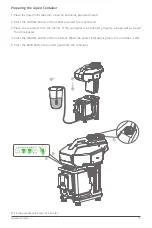
Page 19: ...filler to power the machine on 3 Place the container into the refiller If the container is positioned properly a beep will be heard from the buzzer 4 Press the ON OFF button of the container When the power indicator is green the container is ON 5 Press the Refill button to transfer liquid into the container 1 3 2 5 4 Less In Out More On Off 2L 4L 6L 8L 10L 12L 14L 16L 18L 20L Fault Battery Charge ...

Page 20: ...e operation The filler detects low battery level The operation is suspended All indicators flash eight times and the buzzer beeps eight times before refiller turns off automatically Charge the refiller immediately RED LIGHT ON RED LIGHT ON RED LIGHT ON RED LIGHT ON LED Display Description Warning Beep Once Twice Three times Four times Five times Six times Eight times Fault THREE LIGHT FLASHING Gre...

Page 21: ...under each motor The color of the indicators can be adjusted in the Plant Protection Operation APP Status indicator light definitions are as follows using the red light as an example Spraying Status Indicator Description SOLID QUICK FLASH SLOW FLASH Spray system is Normal UAV is Taking off Landing Spray system is Abnormal observe interface of plant protection operation APP ...

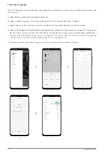
Page 22: ...pdate and click Update to start downloading the new firmware Once the firmware is downloaded and transfered follow the instructions to restart the devices for the firmware update During the UAV firmware update the motor beeps and the white light flashes quickly The beeping will stop once the upgrade is complete Do not disconnect the smartphone and the remote control while downloading or transmitti...

Page 23: ...l plastic HDPE Obstacle Avoidance System XCope Model XCOPE201819 Power consumption 19W Operating frequency 30Hz Obstacle avoidance direction avoid obstacles in front according to the flight direction Obstacle sensing range 1 5 20m Viewing angle 30 horizontal Viewing angle 0 2m below and 0 3m above the obstacle avoidance system vertical Safe distance 2 5m the distance between propeller tip and the ...

Page 24: ...IRP CE 20dBm Transmission power EIRP SRRC 20dBm Transmission power EIRP MIC 20dBm Transmission power EIRP 5 725 5 850GHz Transmission power EIRP FCC 31dBm Transmission power EIRP CE 14dBm Transmission power EIRP SRRC 27dBm Maximum effective signal range near ground level 2 400 2 483GHz FCC 2000m CE 1000m SRRC 1000m MIC 1000m 5 725 5 850GHz FCC 2000m CE 300m SRRC 1300m Transmission distances vary f...

Page 25: ...erchantability fitness for a particular use or non infringement 06 To the maximum extent permitted by law XAG shall not be liable for all losses caused by users failure to use the product in accordance with this document and the Product Manual XAG shall not be liable for any indirect consequential punitive contingent special or penal damages in cluding any losses incurred as a result of your purch...

Page 26: ... frequency in terference Maintain a proper distance from the UAV during operation Do not touch the propeller with your body or any other body parts Do not wear loose clothes during flight to avoid injury caused by the propeller Suggestion for safety reasons it is recommended that the propeller not be installed during the Pre flight Check of the airframe motor and remote control device The propelle...

Page 27: ... Public Account of XAG AGRI In order to strength the management of civil UAVs Civil Aviation Administration of China CAAC has issued the Regulations on Real name Registration of Civil Unmanned Aerial Vehicles which requires the owners of civil UAVs to register in real name at uas caac gov cn and attach the registration marks to the UAVs Failure to comply with the Regulations is subject to punishme...

Page 28: ...ds and processes etc belongs to XAG Co Ltd and is protected by copyright law Without written authorization no individual or institution is allowed to reproduce extract translate distribute or otherwise reproduce or quote any content here of This Manual is subject to upgrade without prior notice info xa com XAGofficial XAG_official XAG Official ...

Reviews: