
Quickstart Guide
WyreStorm 10 x 1 HDBaset Presentation Switcher
with Mic Control and CEC
SW-1001-HDBT
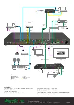
Attention: Open out for installation diagram.
Before Installation
•
Check compatibility of source/display devices and device
settings prior to connection and operation
•
Make sure of firm cable connection to devices but do not force
connectors into ports
•
Always use good quality, high speed Category 2 HDMI cables
within the transmission distance specification for devices used
– we recommend WyreStorm Express HDMI cables
•
Although WyreStorm products are tested with Cat5e, we
recommend Cat6 as standard due to increased bandwidth and
improved capacity for handling large transmissions and power
along a single cable.
•
This unit will auto-scale output according to EDID settings of
connected sync device. See full manual for details on how to
manually override this function.
Set-up
At source location, connect VGA (with corresponding audio input)
HDMI, HDBaseT and DisplayPort devices as required, either directly
to the rear of the SW-1001-HDBT or via a desk plate, ensuring firm
port connection using good quality cables.
NOTE: VGA audio inputs are embedded and passed with
transmissions.
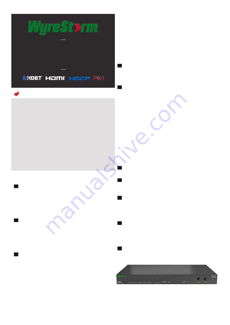
If using an external microphone, connect to MIC input 1 or 2 and
adjust the input level (MIC GAIN) on the front of the unit – microphone
inputs are embedded independently over the selected video source.
Ensure the Phantom Power setting is turned ON if using a
microphone requiring 48V power and OFF If using a dynamic
microphone.
A source in a remote location up to 100m/328ft* from the SW-
1001-HDBT can be distributed and powered using HDBaseT and
POH technology in conjunction with a compatible WyreStorm PoH
transmission device to eliminate the need for mains power supply
at the remote source location. (See full manual for compatible
transmission devices)
*Depending on HDBaseT classification used in the transmission
device - Class A (100m) / Class B (70m)
1
2
3
4
5
6
7
8
9
10
Connect good quality, well-terminated Cat6 cable between the HDBT
or UTP OUT port of the transmission device and the HDBT IN port
of the SW-1001-HDBT and connect IR/RS232 to a control system if
used.
NOTE: Control of display device (projector/screen) from the
remote location is achieved by sending embedded commands
from the HDBaseT transmitter through SW-1001-HDBT and
passed along the HDBaseT link to the receiver at the display
location.
Output connection is via mirrored HDBaseT and HDMI, with HDMI
connection to a local display device up to 15m using High Speed
Category 2 HDMI cables from a quality brand such as WyreStorm
Express.
For HDBaseT output, connect another well terminated Cat6 cable of
no more than 100m/328ft from the HDBT OUT of SW-1001-HDBT
to the HDBT IN of a compatible PoH-enabled WyreStorm receiving
device at display location (See wyrestorm.com for compatible
receiving devices.)
A PoH-enabled receiver or compatible display device can be
remotely powered by the SW-1001-HDBT so no power outlet is
required at the receiver location.
NOTE: Optional power connectivity is available on both
transmission and receiving devices if required, for example if a
cable is too weak to carry power.
Any HDBaseT transmitter or receiver can be used but support of
features (such as PoH, serial control, Ethernet etc.) is dependent
on model. Check the specification of the TX or RX device before
installation.
Connect to a control system via RS232 or LAN as required, ensuring
RS232 connections are in place at source and display locations.
Connect a network cable from a router or Ethernet switch to the
LAN 1 port to add Ethernet to the HDBaseT transmission. Connect a
cable also to LAN 2 if controlling via a LAN enabled control system.
Audio breakout is offered as a fixed line-out or variable pre-out for
connection to power amplifiers with no in-built volume control.
Control of this function is via Web UI or command protocol for the
switch. See full manual for details
To reset IP address or auto-scaling functionality for any reason, press
to reset to default settings.
NOTE: This action cannot be undone so would require set up
to be repeated.
Connect power cable included and switch on the power at the rear of
the unit – a lit red power LED on the front panel will indicate the unit
is powered.


