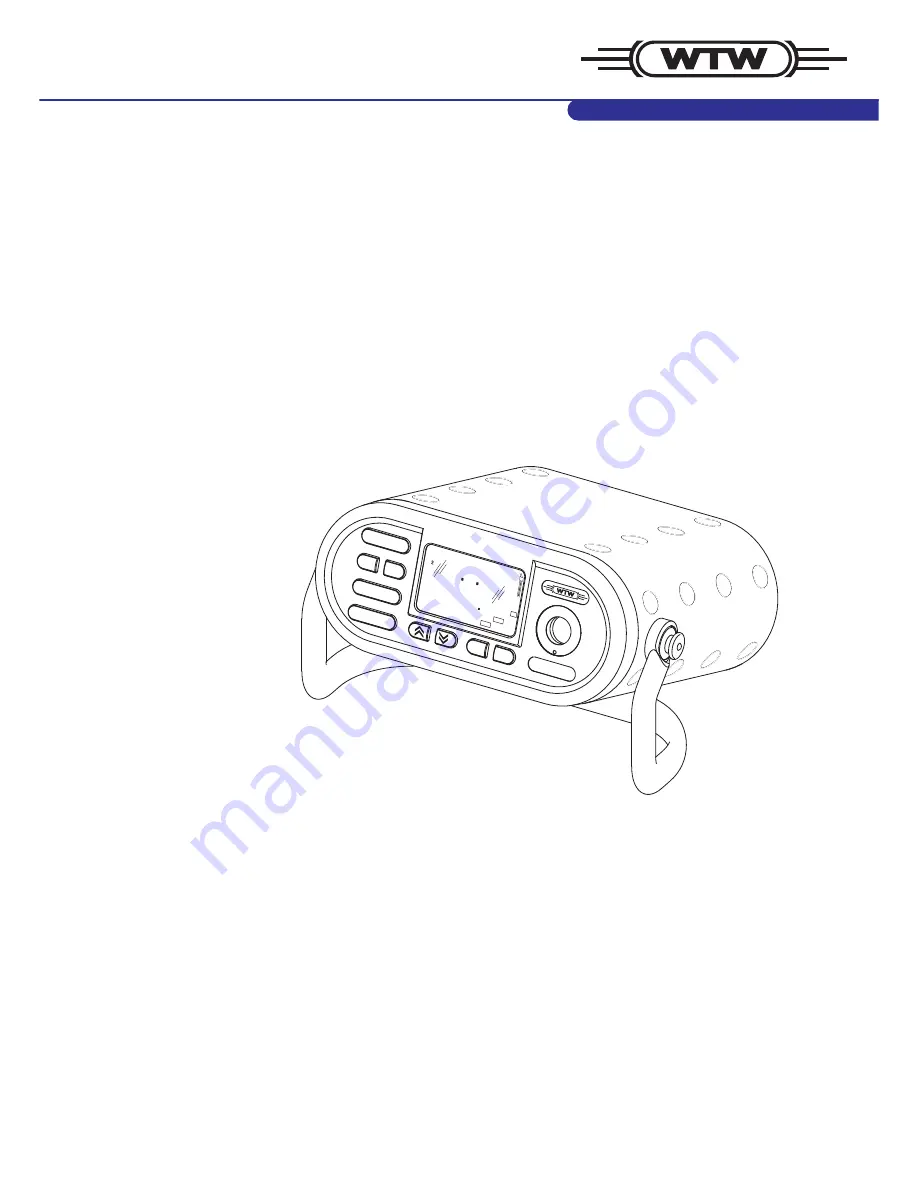
Multi 197i
ba75339e04
07/2009
Operating manual
RUN / ENTER
AUTO READ
CAL
STO
M
RCL
ON / OFF
mg/l
O
7
1 7 6
92
°
C
ARng
TP
REL1
Portable pH / oxygen / conductivity measuring instrument
Page 1: ...Multi 197i ba75339e04 07 2009 Operating manual RUN ENTER AUTO READ CAL STO M RCL ON OFF Multi 197i mg l O 7 1 7 6 92 C ARng TP REL1 Portable pH oxygen conductivity measuring instrument...
Page 2: ...his operating manual and your instrument Also we cannot guarantee that there are absolutely no errors in this manual Therefore we are sure you will understand that we cannot ac cept any legal claims r...
Page 3: ...0 4 3 4 pH calibration 21 4 4 Dissolved oxygen 27 4 4 1 General information 27 4 4 2 Measuring the D O concentration 29 4 4 3 Measuring the D O saturation 30 4 4 4 AutoRead AR Drift control and hold f...
Page 4: ...ion 58 4 10 Reset 62 5 Maintenance cleaning disposal 65 5 1 Maintenance 65 5 2 Cleaning 65 5 3 Disposal 65 6 What to do if 67 6 1 pH system messages 67 6 2 Oxi system messages 69 6 3 Conductivity syst...
Page 5: ...egree of operating comfort re liability and measuring certainty for all applications The proven MultiCal and OxiCal calibration procedures and the pro cedures to determine set up the cell constant sup...
Page 6: ...8 8 8 8 8 88 1 C Time Year LoBat nLF Oxi Cal TEC ARng AR RCL Ident Tref25 Tref20 Auto Store REL2 TP No Day Month Baud REL1 Status display indicator Measured value Function and temperature display Sen...
Page 7: ...ure or one pH electrode combination electrode or pH electrode reference electrode Please make sure that only one pH sensor is connected at the same time z One D O sensor z One conductivity measuring c...
Page 8: ...me time Sensor Instrument Socket Posi tion pH depth armature 1 pH electrode or pH combination electrode 2 pH combination electrode with temperature sensor 2 and 4 Reference electrode 3 Temperature sen...
Page 9: ...operating manual use the following safe ty instruction to indicate various types of danger Warning indicates instructions that must be followed precisely in order to avoid the possibility of slight in...
Page 10: ...onment the formation of condensate can lead to the faulty func tioning of the instrument In this event wait until the temperature of the instrument reaches room temperature before putting the instrume...
Page 11: ...re chargeable battery or with the plug in power supply The plug in power supply supplies the measuring instrument with low voltage 12 V DC At the same time the rechargeable battery is charged Charging...
Page 12: ...n 3 2 POWER SUPPLY z Set the date and time Setting the date and time 1 Connect the plug 1 to the socket 2 of the measuring instru ment 2 Connect the original WTW plug in power supply 3 to an easily ac...
Page 13: ...et the current year with 9 Confirm with RUN ENTER The hours flash on the display 10 Set the current time with 11 Confirm with RUN ENTER The minutes flash on the display 12 Set the current time with 13...
Page 14: ...on proper storage refer to the operating manual of the sensor Moistening the quiver insert Warning Do not store pH electrodes in the quiver for more than 10 hours To store them for a longer period of...
Page 15: ...nt is made with the aid of a relay The active REL socket is shown on the display The measured variable on the display can be selected as follows using the M key Several measuring modes are available w...
Page 16: ...nergy saving feature switches the measuring instrument off if no key has been pressed for an hour The energy saving feature is not active z if the power is supplied by the plug in power supply z if th...
Page 17: ...rthed PC printer measurements cannot be per formed in earthed media as incorrect values would result The RS232 interface is not galvanically isolated 1 Connect the pH depth armature or the pH electrod...
Page 18: ...hat you can either disconnect the 2nd sensor and use the manual temperature input or use an electrode with a temperature sensor If a temperature sensor is connected it is indicated on the display by T...
Page 19: ...trode in the test sample 3 Press the keys repeatedly until pH appears on the status display The pH value appears on the display 4 When measuring without a connected temperature sensor Options z Determ...
Page 20: ...hold function 3 Start AutoRead with RUN ENTER AR flashes until a stable measured value is reached This measured value is transmitted to the interface 4 If necessary start the next AutoRead measurement...
Page 21: ...pending on the instrument setting see section 4 9 CONFIGURATION the instrument displays the relevant buffer nominal value or the current electrode voltage in mV The calibration can be terminated after...
Page 22: ...e according to section 4 8 2 before calibrating After a valid calibration the record is printed Sample printout CALIBRATION PROTOCOL 02 03 02 14 19 Device No 12345678 Calibration pH Cal time 01 03 01...
Page 23: ...e according to the electrode operating manual 30 30 62 61 or 56 50 E3 Perform error elimination ac cording to chapter 6 WHAT TO DO IF 30 or 30 62 or 50 1 Connect the pH electrode to the measuring inst...
Page 24: ...nd 7 if you use a pH electrode with temperature sen sor or the temperature sensor of a conductivity measuring cell or a D O sensor Starting the calibration 1 Press the CAL key The Ct1 display and the...
Page 25: ...8 Immerse the pH electrode into the second buffer solution 9 Press the RUN ENTER key The AR display indicator flashes The electrode voltage mV or the buffer nominal value ap pears on the display Examp...
Page 26: ...Year Ident No Day Month Baud Sal cm 1 K RCL REL2 pH m cm S mg l 2 4 8 C TP REL1 AR Cal TEC Auto 1 O S LoBat nLF Lin Oxi Tref25 Tref20 8 Time Year Ident No Day Month Baud Sal cm 1 K RCL REL2 pH m cm S...
Page 27: ...drift control for checking the stability of the measurement signal This ensures the reproducibility of the measur ing signal For details of how to switch the AutoRead function on off see page 31 Warn...
Page 28: ...te Incorrect calibration of D O probes will result in incorrect measured values Calibrate at regular intervals Temperature sensor The D O sensor has an integrated temperature sensor that always measur...
Page 29: ...s follows to switch on the salt content correction 1 Perform the preparatory activities according to section 4 4 1 2 Immerse the D O sensor in the test sample 3 Press the key repeatedly until the D O...
Page 30: ...ies according to section 4 4 1 2 Immerse the D O sensor in the test sample 3 Press the key repeatedly until the D O saturation in appears on the display Sal S pH AR 1 LoBat nLF Lin Oxi Tref25 Tref20 C...
Page 31: ...suring mode Reproducibility Response time D O concentra tion better than 0 05 mg l 10 seconds Oxygen saturation index better than 0 6 10 seconds 1 Call up the measuring mode with M and or 2 Activate t...
Page 32: ...y indicator flashes The calibration process is fin ished when AR stops flashing Displaying the calibra tion data You can view the data of the last calibration on the display The pro ceeding is describ...
Page 33: ...ote The sponge in the air calibration vessel must be moist not wet Ob serve the instructions in the OxiCal SL operating manual Display Relative slope S 0 8 1 25 S 0 7 0 8 S 0 6 0 7 E3 Perform error el...
Page 34: ...shows the sensor evaluation see page 33 7 Switch to the measuring mode with M S AR Year Ident No Day Month Tref25 Tref20 LoBat Lin nLF mg l ARng Sal pH 1 TEC Auto Store 8 Time Baud Sal cm 1 K RCL REL2...
Page 35: ...he salinity How to proceed is de scribed in section 4 5 3 MEASURING THE SALINITY on page 38 Entering the salt content Note How to switch on the salt content correction is described on page 29 1 Determ...
Page 36: ...the measurement signal This ensures the reproducibility of the measur ing signal For details of how to switch the AutoRead function on off see page 39 Preparatory activities Perform the following prep...
Page 37: ...play 2 Press the RUN ENTER repeatedly until the last calibrated cell constant is displayed e g 0 472 1 cm 3 To return to the measuring mode Press the M key when the correct cell constant is displayed...
Page 38: ...The conductivity value appears on the dis play 1 Perform the preparatory activities according to section 4 5 1 page 36 2 Immerse the conductivity measuring cell in the test sample 3 Press the keys re...
Page 39: ...essing RUN ENTER You can only change to another measuring mode after completion of AutoRead 1 Call up the measuring mode or SAL with M and or 2 Immerse the conductivity measuring cell in the test samp...
Page 40: ...isplay indicator flashes The calibration process is finished when AR stops flashing Displaying the calibration data You can view the data of the last calibration on the display The pro ceeding is desc...
Page 41: ...play or the fixed cell constant 0 475 1 cm without sensor symbol on the display In this case the measurement parameters are initialized See Reset on page 62 3 Immerse the conductivity measuring cell i...
Page 42: ...WHAT TO DO IF 5 To return to the measuring mode Press the M key The de termined cell constant is taken over for the measurement TP ARng nLF C cm S Sal RCL S m mg l O Oxi Year Ident No Day Month Tref20...
Page 43: ...red parameter Designation Default setting pH ORP Int 3 7 days Dissolved oxygen Int 4 14 days Conductivity Int 5 180 days 1 Switch off the measuring instrument 2 Press the M key and hold it down 3 Pres...
Page 44: ...ber You can transmit measured values data records to the data storage in two ways z Save manually z Switch on AutoStore Int 1 see page 46 4 7 1 Saving manually You can transmit a measured value to the...
Page 45: ...ument changes to the measuring mode No Time Cal d 1 I O AR cm 1 4 Tref25 TP ARng nLF C cm S Sal RCL S m mg l Oxi Year Day Month Tref20 LoBat Lin Sal TEC Auto Baud K REL2 pH mV 2 9 6 9 REL1 pH Store Id...
Page 46: ...the required interval between the saving procedures with selection 5 s 10 s 30 s 1 min 5 min 10 min 15 min 30 min 60 min 4 Confirm with RUN ENTER The number of free memory locations appears on the dis...
Page 47: ...toStore function is continued By this however temporal gaps in the re cording of the measured values will occur Switching off AutoStore Switch AutoStore off by z setting the save interval Int 1 to OFF...
Page 48: ...rage location of the data record is displayed for approx 2 s then the respective temperature appears Display further data of the data record ID number date time storage location Press RUN ENTER Toggle...
Page 49: ...required element ap pears on the display After approx 2 s the temperature of the displayed measured value appears 1 Press the RCL key repeatedly until Sto SEr appears on the display 2 Press the RUN EN...
Page 50: ...1 No 4 09 03 02 17 46 7 11 mg l 17 8 C Tauto SAL 17 9 Ident 4 No 5 10 03 02 19 09 2 40 mS cm 25 3 C Tauto nLF Tref25 C 0 475 1 cm Ident 10 No 6 10 03 02 20 48 2 46 mS cm 25 6 C Tauto nLF Tref25 C 0 47...
Page 51: ...mV 4 Press RUN ENTER to display the relative slope of the D O sensor pH TP Sal cm 1 K C Year Ident 1 S Store AR LoBat nLF Lin Oxi Tref25 Tref20 ARng 8 Time No Day Month Baud REL2 m cm S mg l Sal O pH...
Page 52: ...In this case the measuring parameters are initialized see section 4 10 RESET 6 With M you can switch back to the last active measuring mode REL1 REL1 L C L C TP TP AR TEC Auto C pH C pH m cm S mg l mV...
Page 53: ...ear Ident No Day Month Tref25 Tref20 LoBat Lin nLF Sal pH C TEC Auto Store Time Baud cm 1 K REL2 pH mV m cm S C S E R AL REL1 RCL CALIBRATION PROTOCOL 02 03 02 14 19 Device No 12345678 Calibration pH...
Page 54: ...ing mode Proceed as follows to clear all data records Note The calibration data remain stored and can be called up 1 Switch off the measuring instrument 2 Press the STO key and hold it down 3 Press th...
Page 55: ...ed intervals z With the Output data storage function page 48 calibration data or saved measured values are output on the interface 4 8 1 Data transmission interval Int 2 The interval for the data tran...
Page 56: ...at the same time the data trans mission is performed according to the setting of the save interval Int 1 Set the save interval Int 1 to OFF to activate the Data transmission in terval Int 2 4 Confirm...
Page 57: ...ld result Set up the following transmission data at the PC printer Socket assignment 4 8 3 Remote control The measuring instrument can be remotely controlled from a PC This requires the KOM pilot comm...
Page 58: ...nt value in mbar no input possible Calibration intervals pH 1 7 999 dInt 3 O2 1 14 999 dInt 4 1 180 999 dInt 5 Date time Any 1 Switch off the measuring instrument 2 Press the M key and hold it down 3...
Page 59: ...dent No Day Month Tref25 Tref20 LoBat Lin nLF Sal C Store Time Baud cm 1 K REL2 mV m cm S C I S P AL REL1 d RCL pH pH Cal TEC Auto 8 Confirm with RUN ENTER Int 3 and the measured variable pH appear on...
Page 60: ...n t REL1 d I O Time Cal 13 Set the required interval in days d with 14 Confirm with RUN ENTER The reference temperature set for conductivity measurements appears on the display O AR cm 1 Tref25 TP AR...
Page 61: ...he current year with 22 Confirm with RUN ENTER The hours flash on the display 23 Set the current time with 24 Confirm with RUN ENTER The minutes flash on the display 25 Set the current time with 26 Co...
Page 62: ...ost when the measuring parameters are re set Recalibrate after performing a reset Configuration parameters The following configuration parameters InI are reset to the delivery status Measuring mode pH...
Page 63: ...to reset the O2 measuring parameters 5 Using switch between no and YES YES Resetting the O2 measuring parameters no Retaining settings 6 Confirm with RUN ENTER The measuring instrument switches to th...
Page 64: ...Time Cal I AR cm 1 TP ARng nLF C cm S Sal RCL S m mg l Oxi Year Ident No Tref20 LoBat Lin Sal TEC Auto Store Baud K REL2 pH mV n o i in REL1 O pH Day Month 0 9 Tref25 Time Cal I AR cm 1 TP ARng nLF C...
Page 65: ...instrument is sent out in a protective transport packing We recommend Keep the packing material The original packing pro tects the measuring instrument from transport damages Rechargeable battery Remo...
Page 66: ...tenance cleaning disposal Multi 197i 66 ba75339e04 07 2009 Measuring instrument Dispose of the measuring instrument without the rechargeable battery as electronic waste at an appropriate collection po...
Page 67: ...e electrode Gel electrolyte dried out Replace electrode Cause Remedy Electrode Diaphragm contaminated Clean diaphragm Membrane contaminated Clean membrane Moisture in the plug Dry plug Electrolyte obs...
Page 68: ...Membrane contaminated Clean membrane Test sample pH value not stable Measure with air excluded if necessary Temperature not stable Adjust temperature if necessary Electrode test sample Conductivity to...
Page 69: ...ween gold and lead electrode Clean sensor and replace it if necessary Cause Remedy Invalid calibration Oxygen sensor Electrolyte solution depleted Regenerate sensor Membrane contaminated Clean membran...
Page 70: ...function using the salinity equivalent Air bubbles bump on the membrane with high velocity Avoid direct flow to the membrane The carbon dioxide pressure is too high 1 bar Measuring not possible Cause...
Page 71: ...Operating condition undefined or EMC load unallowed Processor reset Switch the instrument on while pressing the RCL key Cause Remedy Time out of the interface Check the instrument connected Cause Reme...
Page 72: ...What to do if Multi 197i 72 ba75339e04 07 2009...
Page 73: ...CE Ambient conditions Storage 25 C 65 C Operation 10 C 55 C Climatic class 2 Power supply Rechargeable battery Nickel metal hydride NiMH Operational life approx 600 hours with one charging Plug in pow...
Page 74: ...e length Max 15m Guidelines and norms used EMC EC guideline 89 336 EEC EN 61326 1 1998 EN 61000 3 2 A14 2000 EN 61000 3 3 1995 FCC Class A Instrument safety E C guideline 73 23 EEC EN 61010 1 A2 1995...
Page 75: ...uracies Variable Accuracy 1 Digit Concentration mg l 0 5 of measured value at ambient temperature of 5 C 30 C Saturation 0 5 of measured value when measuring in the range of 10 K around the calibratio...
Page 76: ...the IOT table 0 1 T C 5 0 105 0 0 1 Accuracies Variable Accuracy 1 Digit S cm mS cm nonlinear compensa tion Accuracy Sample temperature 0 5 0 C 35 C according to EN 27 888 0 5 35 C 50 C extended nLF...
Page 77: ...eviations explains the indicators and the abbreviations that appear on the display and in the manual Specialist terms The glossary briefly explains the meaning of the specialist terms How ever terms t...
Page 78: ...pH mea surements Indicates the selection of the buffer data record for buffer solutions prepared according to DIN 19 266 Cm Display indicator during calibration for pH mea surements Indicates the sele...
Page 79: ...rflow OxiCal Automatic calibration for D O measurements pH pH value S Slope internat k SAL Salinity SELV Safety Extra Low Voltage SLO Slope setting on calibration TC Temperature coefficient internat T...
Page 80: ...ance to conduct an electric cur rent In water analysis the electrical conductivity is a dimension for the ionized substances in a solution D O partial pressure Pressure caused by the oxygen in a gas m...
Page 81: ...t of the molality The practical pH value is the value of a pH measurement Potentiometry Name of a measuring technique The signal depending on the mea sured parameter of the electrode is the electrical...
Page 82: ...lue is converted to a defined reference temperature For potentiometric measurements the slope value is adjusted to the tem perature of the test sample but the measured value is not converted Slope The...
Page 83: ...Keys 6 M Mains operation 11 Measuring 36 conductivity 38 D O concentration 29 D O saturation 30 ORP voltage 20 pH value 19 Salinity 38 Measuring mode when switching on 16 Measuring ranges Conductivity...
Page 84: ...Index Multi 197i 84 ba75339e04 07 2009 ues 55 Two point calibration 21 Two point calibration pH 21 25...