


2015 World Cat 295CC Owners Manual
Chapter 10: 295CC O
PERATION AND
S
CHEMATICS
10.1 O
PERATION OF
S
TANDARD
E
QUIPMENT
10.1.1 Battery Layout and Management
Your 295CC is equipped with three batteries, which are located in the helm leaning post. They can be reached using
the access hatch located on the forward vertical wall of the leaning post. A cranking battery is installed on each side,
and a dedicated house battery is installed in the center. Wire leads run through the hull harness to the battery
management panel which is above the battery access door. See section 6.5 thru 6.5.5 for information regarding the
operation of this panel. The engine cranking leads run aft, through a hull rigging tube, from the management panel to
a positive stud mounted on the bulkhead in each aft rigging compartment. The negative engine leads are connected to
the common battery ground using a negative buss also located in the aft rigging compartment.
The house battery provides the power for a majority of your DC accessories. The main battery lead runs to the
“HOUSE” switch on the battery management panel. From there current is routed to the dash and circuit breaker
through the 80 amp “DC Main” breaker located in the center of the battery management panel. During normal
operation this breaker can remain in the “ON” position, and the “HOUSE” switch can be used to control the flow of
current. The main ground for all DC accessories is tied into the common ground on all batteries.
10.1.2 Additional Emergency Parallel
As an additional feature, the 295CC management panel contains a secondary “EMERG PARALLEL” switch. It
allows you to mechanically link the starboard “cranking” battery to the house battery. Furthermore, engaging both
“EMERG PARALLEL” switches will connect all three batteries into a single bank. The switches should remain in the
“OFF” position when not in use. To prevent voltage spikes or drops which can damage electrical components, you
should trip the DC Mains 1 breaker prior to cranking engines with the house battery in parallel. Once you are
running, the breaker can be reset to allow the full alternator output to power the electronics. This is a safety feature
and should not be used in-lieu of the VSR’s to charge batteries while underway. Doing so, could result in premature
battery failure and increases the risk of electrical failure while at sea.
10.1.3 Bilge Pumps / Float Switches
Your 295CC is equipped with two 1500 GPH bilge pumps located aft. Each pump is connected to a float switch
which automatically triggers the pump when water comes to rest in the bilge. The float switches are connected to the
battery management panel through the hull harness and receive power from the breakers on the right side of the panel.
These breakers are constantly energized and ensure the safety of your boat even when the battery switches are in the
“off” position. The pumps can be manually engaged using the switch at the dash.
The aft bilge pumps are located behind the aft rigging compartment and can accessed through the inspection plates in
the motorwell, forward of the engines. The wiring for these pumps is secured to the centerline stringer which is
visible from the hatch. Inspect the operation of your bilge pumps and their connections at least annually. To do so,
activate the pump by lifting the external float switch once released the pump should shut off. Keeping your bilge
areas clean can also help extend the life of your pump.
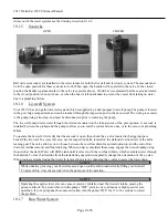
10.1.4 Freshwater System
The freshwater pump is mounted to the hullside and can be reached through the access door in the starboard gunwale.
The pump is connected to the 20 gallon freshwater tank located in the hull forward of the starboard fuel tank. The
tank is filled through a fitting located on the starboard side of the deck. Similar to residential well pumps, the
freshwater pump pressurizes the system to 45 psi. then shuts down until the pressure drops below that level. Most
owners leave the pump “on” throughout the day, and use the system when necessary. On the 295CC, the freshwater
pump feeds the pull out shower located on the aft transom wall, freshwater wiper rinse and the marine head. To view
Page 10-55
Summary of Contents for 295CC 2015
Page 1: ...2015 OWNER S MANUAL 295CC ...
Page 11: ...2015 World Cat 295CC Owners Manual 3 3 295CC FEATURES Page 3 10 ...
Page 41: ...2015 World Cat 295CC Owners Manual 7 5 UPHOLSTERY CARE OPTIONAL SOLID UPHOLSTERY Page 7 40 ...
Page 42: ...2015 World Cat 295CC Owners Manual Page 7 41 ...
Page 46: ...2015 World Cat 295CC Owners Manual Page 7 45 ...
Page 47: ...2015 World Cat 295CC Owners Manual Page 7 46 ...
Page 48: ...2015 World Cat 295CC Owners Manual Page 7 47 ...
Page 49: ...2015 World Cat 295CC Owners Manual Page 7 48 ...
Page 51: ...2015 World Cat 295CC Owners Manual Chapter 8 HURRICANE PREPAREDNESS Page 8 50 ...
Page 52: ...2015 World Cat 295CC Owners Manual Page 8 51 ...
Page 53: ...2015 World Cat 295CC Owners Manual Page 8 52 ...
Page 63: ...2015 World Cat 295CC Owners Manual 10 4 2 Water Systems Diagram Page 10 62 ...
Page 64: ...2015 World Cat 295CC Owners Manual 10 4 3 Thru Hull Diagram Page 10 63 ...
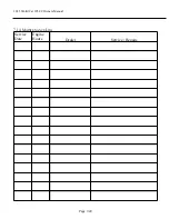
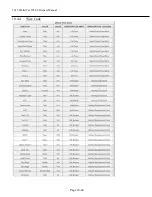
Page 65: ...2015 World Cat 295CC Owners Manual 10 4 4 Wire Code Page 10 64 ...