background image

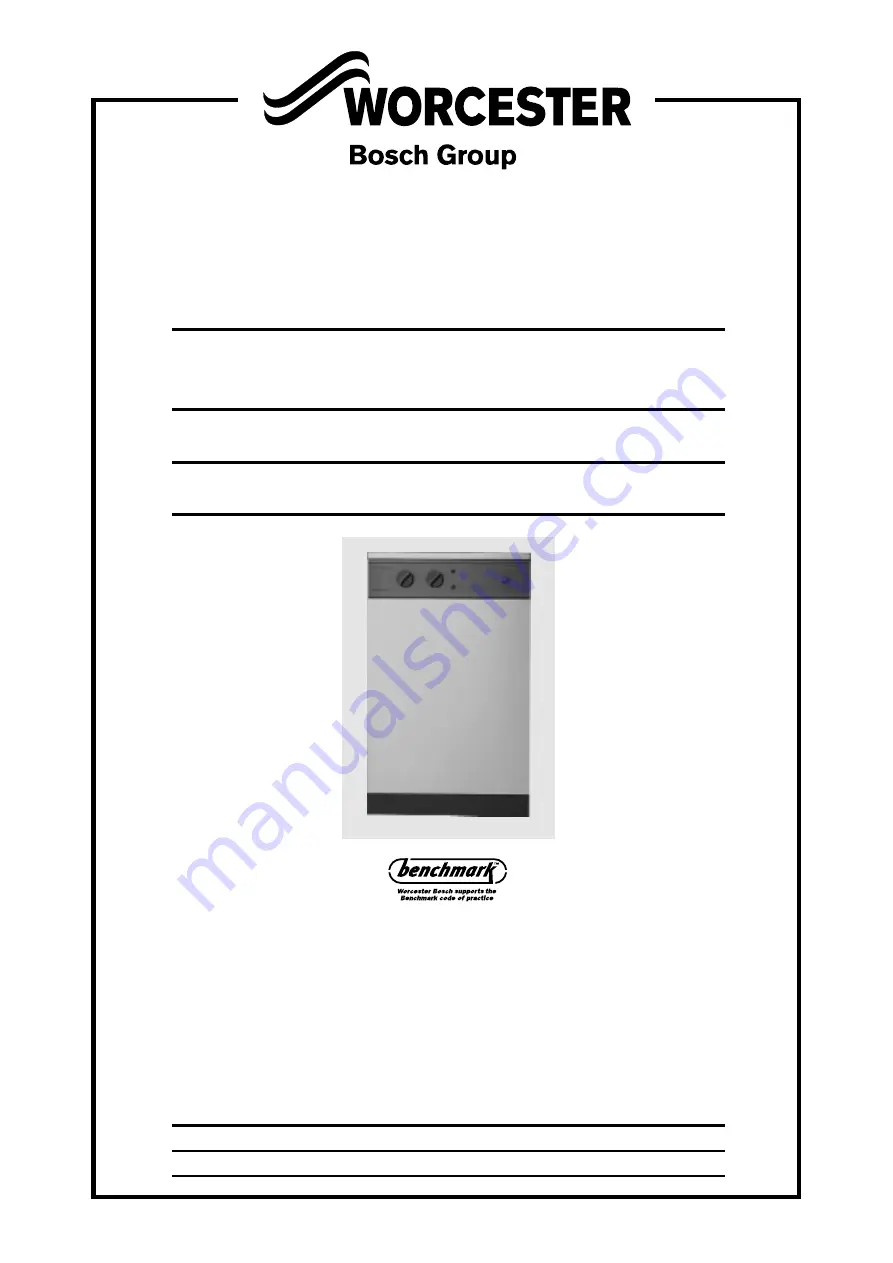
OIL HEATSLAVE

12/14  15/19  20/25  26/32

CONVENTIONAL FLUE AND ROOM SEALED BF FLOOR

STANDING COMBINATION BOILER FOR CENTRAL

HEATING AND MAINS FED DOMESTIC HOT WATER

INSTALLATION AND

SERVICING INSTRUCTIONS

BOILER OUTPUT

Domestic Hot Water and Central Heating

12/14

MINIMUM 12 kW

(41,000 Btu/h)

MAXIMUM 14 kW

(48,000 Btu/h)

15/19

MINIMUM 15 kW

(51,000 Btu/h)

MAXIMUM 19 kW

(65,000 Btu/h)

20/25

MINIMUM 20 kW

(68,000 Btu/h)

MAXIMUM 25 kW

(85,000 Btu/h)

26/32

MINIMUM 26 kW

(89,000 Btu/h)

MAXIMUM 32 kW

(109,000 Btu/h)

THESE INSTRUCTIONS APPLY TO UK MODELS ONLY

THESE INSTRUCTIONS ARE TO BE LEFT WITH THE APPLIANCE

Summary of Contents for OIL HEATSLAVE 12/14

Page 1: ...TIONS BOILER OUTPUT Domestic Hot Water and Central Heating 12 14 MINIMUM 12 kW 41 000 Btu h MAXIMUM 14 kW 48 000 Btu h 15 19 MINIMUM 15 kW 51 000 Btu h MAXIMUM 19 kW 65 000 Btu h 20 25 MINIMUM 20 kW 6...

Page 2: ...orm to the highest standards the system and components should conform to those mentioned in the instructions The Benchmark initiative is the new code of practice to encourage the correct installation...

Page 3: ...and hot water in the lower position Central Heating and Domestic Hot Water Mode The appliance will supply heat to the central heating system as required The water supplied to the central heating circu...

Page 4: ...145Kg 319lbs RS 134Kg 295lbs 137Kg 302lbs 149Kg 328lbs OVERALL APPLIANCE HEIGHT 855mm 33 7in 855mm 33 7in 855mm 33 7in OVERALL APPLIANCE WIDTH 520mm 20 5in 520mm 20 5in 520mm 20 5in OVERALL APPLIANCE...

Page 5: ...i Fuel Flow Rate Flue Gas Temp C CO2 Approx Air Setting Appliance Input kW Btu hr kW Btu hr Output Kg h l h 28 Sec Kerosene 0 60 80 EH 130 1 87 2 37 190 11 0 11 5 5 5 22 5 77 000 20 68 000 28 Sec Kero...

Page 6: ...the three screws located in the upper flange of each side panel Ease the panel clear of the electrical control box and slide forwards to release from the locating lugs on the base plate 5 4 The contro...

Page 7: ...ck valve 8 Heatslave tank drain point Unscrew 3 4 turn to drain 2 Automatic air vent 9 Alternative central heating return tapping 3 Diverter valve 10 Flow switch 4 Pump 11 Mains cold inlet isolating v...

Page 8: ...l Side panel locking screw A 8 1 Hot water check valve 8 Heatslave tank drain point Unscrew 3 4 turn to drain 2 Automatic air vent 9 Alternative central heating return tapping 3 Diverter valve 10 Flow...

Page 9: ...7 Alternative central heating return tapping 2 Automatic air vent 8 Flow switch 3 Diverter valve 9 Mains cold inlet isolating valve 4 Pump 10 Pressure relief valve 5 System pressure gauge 11 Air vent...

Page 10: ...er check valve 8 Alternative central heating return tapping 2 Automatic air vent 9 Flow switch 3 Diverter valve 10 Mains cold inlet isolating valve 4 Pump 11 Pressure relief valve 5 System pressure ga...

Page 11: ...to allow proper circulation of ventilation air The clearances required for installation and servicing will normally be adequate for ventilation See Section 4 4 A flue system must be provided in accord...

Page 12: ...extension kit a Rear Discharge 4 to 7 Single Skin Wall For use with non standard single skin walls up to 182 mm thick Where noise emission from the flue terminal is likely to be of concern it is reco...

Page 13: ...S The appliance is supplied ready for installation as a low level discharge balanced flue system by the simple addition of one of the flue terminal options shown in Fig 9 Details of the installation p...

Page 14: ...ed to protect the surface 5 If a terminal is fitted less than 2 metres above a surface to which people have access fit a terminal guard as shown in Fig 11 A suitable guard is available from Worcester...

Page 15: ...e length of pipe run b The oil supply pipe should be laid as level as possible to avoid air pockets and unnecessary friction losses c The following components should be fitted in the fuel line between...

Page 16: ...alve to BS 5410 Part 1 Isolating valve Isolating valve Fire detection element Filter Burner Burner Wall Wall b Double pipe system Isolating valve Non return valve Non return valve Fire detection eleme...

Page 17: ...recommended a room thermostat or programmable room thermostat is used in the main zone and thermostatic radiator valves are used in further heating zones On existing systems where a room thermostat is...

Page 18: ...Pt 1 for more information Where the system volume exceeds the value given in Table 13 an additional expansion vessel of suitable volume should be fitted to the heating return pipework as close to the...

Page 19: ...vents are included on high points in the appliance pipework 11 3 The appliance incorporates a circulating pump No other circulating pump is required The pump is factory set to the maximum setting No 3...

Page 20: ...required a mixing valve can be fitted If there are long pipe runs to the taps or shower it is suggested that they be insulated to prevent the rapid cooling of residual hot water in the pipes after th...

Page 21: ...the appliance must allow complete isolation of the appliance preferably via a double pole isolator with a contact separation of 3mm in all poles supplying the boiler and controls only 13 Electrical 2...

Page 22: ...1 X13 PIN 5 X13 PIN 2 X10 PIN 3 X8 PIN 5 X2 PIN 2 X2 PIN 6 X8 PIN 2 X4 PIN 2 0 1 LIVE SUPPLY FOR POST PURGE UNIT X3 PIN 3 X4 PIN 3 X4 PIN 1 4 1 2 3 3 4 4 3 1 1 2 4 1 X2 PIN 5 X1 PIN 1 X9 PIN 1 X2 PIN...

Page 23: ...ia mounted switch are currently still connected See Fig 21b Disconnect the grey lead from the terminal block and connect in its place the central heating control lead from the programmer Disconnect th...

Page 24: ...24 14 Functional Flow Chart...

Page 25: ...25...

Page 26: ...26...

Page 27: ...lue System Installation Install the appliance flue system as described in Section 7 15 4 Heating System Installation Before the appliance is fitted to the heating system flush the system and mains wat...

Page 28: ...ble container below the bulkhead fitting and open the valve 7 Draw off at least 2 5 litres of oil until a steady flow of clear uncontaminated oil can be seen and turn off the isolating valve NOTE This...

Page 29: ...ollect oil from the oil inlet pipe connection of the de aerator c Prime the de aerator and reconnect the de aerator to the flexible oil inlet hose 16 10 Adjust the air shutter and pump pressure to the...

Page 30: ...operative during frost conditions then drain the appliance and system 17 1 Hand the Users Instructions and the Benchmark Log Book to the user or purchaser for retention instruct them in the efficient...

Page 31: ...ut off Valve a Remove the nozzle b Fasten an M5 screw with a minimum length of 30mm into the threaded hole A and pull the screw to withdraw the check valve c Check that the nozzle holder is clear of a...

Page 32: ...the nozzle line and rotate the adjusting disc one turn anti clockwise to move forward by 1 mm Fig 24 Electro Oil Inter B9B Burner 15 19 model Combustion Head Draught tube Nozzle Nozzle block Spark gap...

Page 33: ...nsformer Connecting pipe Solenoid valve Air control indicator Air adjustment screw 4mm hexagonal head Pressure adjustment screw Photocell Motor Combustion head Control box Pump Lockout reset button Ou...

Page 34: ...the gasket and tighten the two locking screws using a 5mm Allen key NOTE It is important that a good seal is made between the burner and the boiler to prevent re circulation of the flue gases from the...

Page 35: ...Pressure Gauge Check that the electrical supply has been turned off Remove the appliance front panel and withdraw the burner Drain the boiler Turn off the isolating valves mounted on the outlet of th...

Page 36: ...phial from the pocket Remove the heyco split bush and slide the copper capillary tube through the slot freeing the capillary tube from the electrical control box Remove the spade connectors and note...

Page 37: ...everse order having first set the switch on the rear of the unit to P as described in the fitting instructions Use only the specified programmer Do not attempt to fit any other model or make 16 Baffle...

Page 38: ...r does not respond to a call for heat Boiler thermostat faulty Check by linking out high limit and control thermostats Programmer open circuit Faulty control box Replace if necessary Flue draught inco...

Page 39: ...39...

Page 40: ...s and or appearances are changed in the interests of continued improvement All goods sold are subject to our official Conditions of Sale a copy of which may be obtained on application 8 716 104 440b 0...

Reviews: