ABOUT THE APPLIANCE
6 720 803 688 (2012/11)
4
2.3
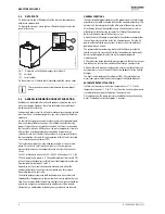
DATA PLATE
On the data plate you will find details of the part number, appliance
output and approval data.
On the hybrid manager, a data plate is affixed to the right hand side
panel of the casing.
Fig. 1
Data plate on the hybrid manager (internal unit)
[1]
Unit data
[2]
Serial number
On the external unit, the data plate is located under the service cover.
2.4
GENERAL INFORMATION ON HEAT PRODUCTION
Buildings can be heated efficiently with condensing boilers and air to
water heat pumps. However, these two technologies have different
performance characteristics.
Condensing boilers as well as air to water heat pumps use energy gained
from fossil fuels. In condensing boilers, gas is burnt directly inside the
appliance.
Air to water heat pumps use electrical energy which has been obtained
from a number of different sources. This includes fossil-fuel-burning
power stations. These are typically around 40 % efficient in converting
fuel to useful electricity. Although an air to water heat pump is far more
efficient than a condensing boiler at converting its input energy
(electricity) into heat, the electricity used has a larger amount of fossil-
fuel consumption attached. This consumption of fossil fuels is referred
to as the primary energy factor (PEF).
The fan draws ambient air via the evaporator of the air to water heat
pump. This extracts heat from the ambient air. The compressor
mechanically increases the temperature and transfers it to the water
circuit.
The PEF of electricity is generally 2.3, the PEF of oil and gas is 1.1, the
PEF of mixed electric power 2.6. The coefficient of performance (COP)
of an air to water heat pump is, subject to outside temperature and water
flow temperature, between 2 and 5.5.
Depending on the current situation and heat demand, either the
condensing boiler or the air to water heat pump may offer a more
favourable energy-to-cost ratio.
The hybrid package integrates both technologies in one system and
thereby offers the opportunity to use either heat source optimally at any
time. Users can decide for themselves whether the emphasis should be
on primary energy consumption and/or whether costs take priority,
alternatively, a combination of primary energy and costs can be used.
GENERAL FUNCTIONS
The hybrid control module determines the proportion of the total energy
expenditure that will be covered by either the condensing boiler or the
external unit, thereby optimizing the efficiency of the heating system.
After flowing through the hybrid manager, the heating water returns
either directly to the heating system or first through the condensing
boiler and then onwards to the heating system.
A high efficiency (HE) pump integrated into the hybrid manager provides
the heating water circulation inside the hybrid manager. Only the HE
pump inside the hybrid manager runs as long as the air to water heat
pump operates on its own.
The pump inside the condensing boiler and the HE pump inside the
hybrid manager run concurrently if either the condensing boiler on its
own or condensing boiler and air to water heat pump operate
simultaneously.
A filter with sieve inside the hybrid manager protects the heat exchanger
and the heating system from contamination through small particles.
A flow switch with magnetic toggle switch ensures that the external unit
only operates as long as the water flow rate is adequate for the Hybrid
Manager.
The heat transfer between the refrigerant (R410A) and the heating
water takes place inside the heat exchanger of the Hybrid Manager.
AUTOMATIC DEFROST FUNCTION
Ice forms on the external unit at low temperatures (
7 °C). In the
temperature range of +7 °C to -9 °C, heat from the heating system water
is used briefly to automatically defrost the external unit.
During defrosting, the boiler remains available for heating the heating
water. The defrost cycle takes approx. 5 minutes.
The service cover may only be removed by a competent
person.
6720803688-01.1W
o
50W
0.43 A
R410A 2.50 kg (30m)
4.15 MPa
2.30 MPa
IPX4D
230V 50Hz
3A
(A2W35) = 3.852kW
(A7W35) = 4.704kW
(A2W35) = 3.14
(A7W35) = 4.42
5570 - XXX - XXXXX - 7716160030
2
1


