


Operation Manual 37107F
MFR 3 - Multi Function Relay
Page 46/165
© Woodward
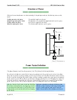
Chapter 5.
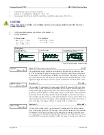
Display and Push-Buttons
The pressure-sensitive membrane of the front panel consists of a plastic coating. All keys have been designed as
touch-sensitive membrane switch elements. The display is an LC display, comprised of 2 lines with 16 characters
each, which are indirectly illuminated in red. The contrast of the display can be infinitely adjusted via a rotary
potentiometer positioned on the left side. The configuration plug is located on the left side of the unit. The direct
configuration cable (DPC) connects there.
MAN
Stop
MFR 3
V / kV
A (L1)
A (L2)
A (L3)
Mains Parallel
ON
V1
V2
V3
AUTO
ACK
Setpoint
Setpoint
Monitoring
Manual
Automatic
Operating and Alarm Messages
Multifunction Relay and Control
27
26
25
24
23
21
18
17
16
15
11
1
2
3
5
10
29
6
7
8
9
28
13
12
14
30
Figure 5-1: Front panel MFR 31
MFR 3
V / kV
A (L1)
A (L2)
A (L3)
ON
ON
V1
V2
V3
AUTO
MAN
ACK
Setpoint
Setpoint
Monitoring
Manual
Automatic
Operating and Alarm Messages
Multifunction Relay and Control
27
26
25
24
23
20 21
18 19
17
16
15
11
1
2
3
5
10
29
6
7
8
9
28
13
12
14
30
Figure 5-2: Front panel MFR 32


