


Operation Manual 37107F
MFR 3 - Multi Function Relay
Page 38/165
© Woodward
Analog Controller Outputs
≡≡≡≡≡≡≡≡≡≡≡≡≡≡≡≡≡≡≡≡≡≡≡≡≡
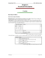
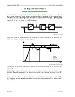
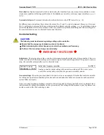
The control unit may be equipped with an analog controller output in addition to a three-position controller out-
put. Additional configuration screens appear in configuration mode. The analog PID controller forms a closed-
loop control loop along with the controlled system (usually a first-order lag element). The parameters of the PID
controller (proportional-action coefficient K
PR
, derivative-action time T
V
and reset time T
n
) can be modified indi-
vidually. The configuration screens are used for this purpose.
Kp
T1
Controlled system (PT1)
PID controller
Kpr
Tn
Tv
Lag element (Tt)
Influence
quantity
Tt
Figure 4-4: Closed loop
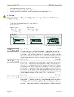
If an abrupt disturbance variable is applied to the control loop, the reaction of the controlled system can be rec-
orded at the output as a function of time (step response).
0
t/s
x
T
T
1
0
T
x
x
d
m
x
d
x
m
T
Rise time
Overshoot
System deviation
rise
rise
Tolerance band
Settling time
sett
sett
Figure 4-5: Step response (example)
Various values can be obtained from the step response; these are required for adjusting the controller to its opti-
mum setting:
Rise time T
rise
:
The period of time starting when a control variable leaves its steady-state condition following a
disturbance variable being applied to it and ending the first time the value re-enters the new steady-state condi-
tion.
Transient time T
sett
:
The period of time starting when a control variable leaves its steady-state condition follow-
ing a disturbance variable being applied to it and ending when the value permanently re-enters the new steady-
state condition.


