background image

2 Instrument Configuration 

Copyright © WOODLEY EQUIPMENT COMPANY LTD. 


49


Table 2-4 Other indicator lights on the main control panel 

Position Code of 
Indicator Light 

Meaning 

Normal Status 

D79 

It indicates the ARM working status and flashes after 
proper system loading. 

Flashing 

D90 

It indicates the FPGA working status and flashes after 
proper system loading. 

Flashing 

D52 

It indicates the MPU working status and flashes after 
proper system loading. 

Flashing 


Indicator lights are very useful in practice; hardware problems can be identified by the status of the 
indicator lights. For details, see 

2.3.1.5 Identification of Main Control Panel Problems

. 

2.3.1.4 Testing Points on the Main Control Panel 

There are two types of testing points on the main control panel: Digital and analog. 

Digital testing points 

The digital testing points on the main control panel listed here are commonly used ones, in particular 
for power supply and key signals. 

Table 2-5 Digital testing point on the main control panel 

Position Code of 
Testing Points 

Description 

TP15 

The testing point for 5V digital input, with the expected voltage of 
5V 

TP9 

TPS65910 VRTC output, with the expected voltage of 1.8V 

TP61 

DDR3 reference voltage, with the expected value of 0.75V 

TP7 

TPS65910 VDIG1 output, with the expected value of 1.8V 

TP8 

TPS65910 VDIG2 output, with the expected value of 1.8V 

TP6 

TPS65910 VAUX33 output, with the expected value of 3.3V 

TP5 

TPS65910 VMMC output, with the expected value of 3.3V 

TP3 

TPS65910 VAUX2 output, with the expected value of 3.3V 

TP4 

TPS65910 VAUX1 output, with the expected value of 1.8V 

TP1 

TPS65910 VDAC output, with the expected value of 1.8V 

TP2 

TPS65910 VPLL output, with the expected value of 1.8V 

TP20 

The testing point for 3.3V digital power supply, with the expected 
voltage of 3.3V 

TP19 

The testing point for 2.5V digital power supply, with the expected 
voltage of 2.5V 

Summary of Contents for InSight V5

Page 1: ...DMR MB 007 1 5...

Page 2: ...ematology Analyser Declaration We reserve the right to final interpretation of this service manual We shall be responsible for the safety security and performance of the product only when all of the f...

Page 3: ...re replaced with no prior consent from us or machine maintenance is performed by personnel with no prior authorisation Any failure by hospitals or organisations responsible for using this instrument t...

Page 4: ...GB Measurement Channel 13 2 2 5 RBC PLT Measurement Module 13 2 2 6 Sampling and Blood dispensing Module 14 2 2 7 Power Supply and Waste Discharge Module 14 2 2 8 Status Monitoring Module 15 2 2 9 Hyd...

Page 5: ...82 3 6 2 Replacing the Liquid Pump Assembly 84 3 6 3 Replacing the Negative pressure Chamber Assembly 85 3 7 Sheath Flow Syringe Assembly Replacement 87 3 7 1 Replacing the syringe 87 3 7 2 Replacing...

Page 6: ...opyright WOODLEY EQUIPMENT COMPANY LTD v 5 5 1 Installing LIS Workstation 108 5 5 2 Host Communication Settings 108 5 5 3 Connecting Analyser with LIS 109 6 Alarms and Solutions 111 7 Maintenance Inve...

Page 7: ...is Manual This service manual should be used by professionals who possess A comprehensive knowledge of electrical circuits and hydraulics A comprehensive knowledge of reagents A comprehensive knowledg...

Page 8: ...r should follow the instructions below each symbol to prevent any danger of infection The following symbols can be found on the analyser reagents QC materials or calibrator Symbol It means Caution Bio...

Page 9: ...horized Representative in the European Community Date of manufacture Manufacturer Storage temperature Humidity level for storage 106kPa 50kPa KPa Atmospheric pressure level for storage Consult the Ope...

Page 10: ...device to the socket using a separate fuse and surge protection switch If the device shares a fuse and surge protection switch with other equipment e g life support equipment any malfunction may cause...

Page 11: ...lt in any electrostatic damage please wear an antistatic wrist strap or maintain the device on an antistatic workstation This analyser must be operated by trained medical testing professionals doctors...

Page 12: ...T COMPANY LTD 6 2 Instrument Configuration 2 1 Mechanical Components The InSight V5 Haematology Analyser consists of the main unit and its accessories Figure 2 1 Front of the analyser 1 Aspirate key 2...

Page 13: ...rk interface 2 USB interface 3 Right side door buckle 4 Left side small door buckle Figure 2 3 Back view of the analyser 1 Power switch 2 Power supply input connector 3 Cooling fan 4 Waste outlet conn...

Page 14: ...er rear shell removed 1 Sampling assembly 2 Main control panel Figure 2 5 Right side view of the analyser right side door removed 1 Power assembly 2 Sampling assembly 3 Counting bath assembly 4 Electr...

Page 15: ...and waste discharge module and the status monitoring module Detailed description DIFF WBC measurement module Consists of the dosing syringe WBC reaction bath flow chamber tubing and valve HGB measure...

Page 16: ...ptocoupler and sensor 2 2 1 Schematic Diagram of the Hydraulic System Figure 2 7 Schematic diagram of the hydraulic system V5 LY1 V5 DIL Dispensing WBC BASO measurement module V5 DIL Diluted sample RB...

Page 17: ...l Pipe LV14 LV13 LV10 LV20 LV21 T29 T19 T29 T29 T29 J3 T80 T195 J10 T80 T80 T65 J2 J2 T197 J10 T73 T39 T82 T87 T67 T67 T80 T89 J10 T171 T38 T239 T171 T170 T177 T199 J10 J10 T170 T57 T105 T241 J6 J2 T7...

Page 18: ...r bubbles through the intermittent valve opening to mix the sample well 3 Measurement Aspirate the incubated sample from the WBC bath using the sampling syringe then close LV12 and open LV01 and LV05...

Page 19: ...WBC bath where they are mixed evenly After aspirating the diluted sample for the first time V5 LY1 Lyse is added into the WBC bath for incubation 2 Mixing Open Valve LV19 to generate air bubbles thro...

Page 20: ...f the sample probe the sampling syringe the sampling tube the swab the horizontal motor and the vertical motor This is how the sampling and blood dispensing module works Open LV04 and aspirate the sam...

Page 21: ...ls and an alarm is activated when it reaches empty Monitoring of V5 LY1 A reflecting optocoupler is used to monitor the V5 LY1 level as it gets lower the optocoupler s status changes until an alarm is...

Page 22: ...S 20 01 0312 A On off switch for fluid control None 6 Three way valve S 20 01 0313 A Directional hydraulic valve None 7 Liquid pump 23 99 0008 A Discharges waste and creates a vacuum None 8 LS Lyse sy...

Page 23: ...e in between the sample flows from the front bath through the aperture to generate electric pulses that facilitate RBC and PLT counting None 12 Negative pre ssure chamber 20 01 1106 A This chamber bui...

Page 24: ...air leakage None 16 Air pump 24 01 000 2A Build positive pressure None 17 Positive pre ssure chamber 20 01 120 4A Build the positive pressure needed for bubble generation in DIFF bath WBC HGB bath and...

Page 25: ...igue 4 Thin 50 Tube 63 01 0008 A 1 6 3 2 Soft Tube 5 Thick 50 Tube 63 01 0009 A 2 4 4 Soft Tube 6 3603 Tube 63 01 0010 A 3 2 6 4 A soft tube used for the external inflow of diluent and waste discharge...

Page 26: ...d deformation 14 2 0mm i d PTFE Tube 63 01 0020 A 2 4 This tube is hard has good resistance to erosion and can be used as an aspiration tube inside the bottle of lyse 15 1 6mm EVA Tube 63 01 0051 A 1...

Page 27: ...connector for 1 6 2 4mm i d tubing 8 MTLL230 1Inte grated locking ring 53 05 0016 A White nylon Integrated locking ring 9 MTLL013 3 Integrated locking ring 53 05 0044 A Red nylon Integrated locking ri...

Page 28: ...de Dilution is performed in vitro and the diluted sample is then aspirated for CBC DIFF measurement Whole blood CBC Mode Whole blood sample aspiration for CBC measurement Predilute CBC Mode Dilution i...

Page 29: ...FF Mode The dilution procedure in Predilute CBC DIFF mode is shown in Figure 2 10 Figure 2 10 Dilution Procedure in Predilute CBC DIFF Mode 2 2 10 3 Dilution Procedure in Whole blood CBC Mode The dilu...

Page 30: ...de 2 2 10 5 Measurement Procedure in Whole blood CBC DIFF Mode In whole blood mode a total of 5 time slots for sample measurement are set at 0s 4s 5s 10s 11s 22s 20s 64s and 64s 72s respectively durin...

Page 31: ...8 T238 T40 T80 T21 T156 T240 T242 T65 T236 T150 T152 T162 T66 T83 T197 T59 T214 T221 T210 T210 T70 T70 T70 T70 T72 T72 T72 T171 T168 T177 T197 T186 T195 T72 T72 T80 T80 T80 T80 T176 T70 250ul T80 J3 T...

Page 32: ...T156 T240 T242 T65 T236 T150 T152 T162 T66 T83 T197 T59 T214 T221 T210 T210 T70 T70 T70 T70 T72 T72 T72 T171 T168 T177 T197 T186 T195 T72 T72 T80 T80 T80 T80 T176 T70 250ul T80 J3 T80 J3 Negative pres...

Page 33: ...0 J10 T80 J6 2 3 1 2 COM 1 NC 3 NO Three way valve Tow way valve 2 1 Note LV liquid value P pump T pipe J connector Name Quantity Note Valve Pump Syring 21 6 2 2 IN 1 OUT J3 T43 T26 T65 Negative press...

Page 34: ...T176 T70 250ul T80 J3 T80 J3 LV14 LV13 LV10 LV20 LV21 T29 T19 T29 T29 T29 J3 T80 T195 J10 T80 T80 T65 J2 J2 T197 J10 T73 T39 T82 T87 T67 T67 T80 T89 J10 T171 T38 T239 T171 T170 T177 T199 J10 J10 T170...

Page 35: ...10 T170 T57 T105 T241 J6 J2 T70 J10 T80 J6 2 3 1 2 COM 1 NC 3 NO Three way valve Tow way valve 2 1 Note LV liquid value P pump T pipe J connector Name Quantity Note Valve Pump Syring 21 6 2 2 IN 1 OUT...

Page 36: ...n the swab 2 2 11 2 Cleaning and Maintenance of the WBC Bath Go to Service Maintenance Clean and click the Clean WBC bath button See Figure 2 19 Figure 2 19 Cleaning and maintenance interface 2 2 11 3...

Page 37: ...liquid flowing onto the base plate when the tube connected to the valve is pulled out the tube pulled out needs to be placed into the small sample cup and tissue paper should be used as a pad to prop...

Page 38: ...relevant parts with tissue paper and disassemble the pump 2 Use the Phillips screwdriver to open the pump cap to observe any clogging resulting from impurities as shown in Figure 2 24 Figure 2 24 Pum...

Page 39: ...to connector No 1 of Valve 20 this tube is the transfer tube for white Teflon tube 1 5 and thin 50 tube covered with marking ring 3 and connect the plastic syringe to the 50 transfer tube through the...

Page 40: ...ng persists the probe cleanser needs to be manually pushed through to clean the RBC channel aperture and the following steps should be taken 4 Empty the RBC bath There are two ways of emptying the RBC...

Page 41: ...liquid pump is clogged Follow the steps specified in 2 2 12 3 Liquid Pump Clogging Inspection and Troubleshooting to inspect and resolve any clogging of the liquid pump After troubleshooting run the C...

Page 42: ...Tow way valve 2 1 Note LV liquid value P pump T pipe J connector Name Quantity Note Valve Pump Syring 21 6 2 2 IN 1 OUT J3 T43 T26 T65 Negative pressure Sensor Positive pressure Sensor Dual Pipe Lyse...

Page 43: ...counting bath is drained by opening the user interface If the liquid level in the WBC bath is found to be too high immediately shut down the device to prevent any further overflowing 2 2 12 7 Overflow...

Page 44: ...valve Tow way valve 2 1 Note LV liquid value P pump T pipe J connector Name Quantity Note Valve Pump Syring 21 6 2 2 IN 1 OUT J3 T43 T26 T65 SE Sampling Syringe Lyse Syringe Negative pressure Sensor D...

Page 45: ...39 T82 T87 T67 T67 T80 T89 J10 T171 T38 T239 T171 T170 T177 T199 J10 J10 T170 T57 T105 T241 J6 J2 T70 J10 T80 J6 2 3 1 2 COM 1 NC 3 NO Three way valve Tow way valve 2 1 Note LV liquid value P pump T p...

Page 46: ...an 1 71mm indicates that the swab needs to be replaced c When reinstalling or replacing the swab first put the inflow tube and outflow tube in place then put on the swab insert the probe into the swab...

Page 47: ...l Pipe Positive pressure Sensor V5 LY1 V5 LY2 V5 DIL 3 Check if the pump is working if not replace the pump 4 Check if the positive pressure sensor and the corresponding electrical circuit are in norm...

Page 48: ...ame Quantity Note Valve Pump Syring 21 6 2 2 IN 1 OUT J3 T43 T26 T65 Positive pressure Sensor Dual Pipe Negative pressure Sensor Lyse Syringe SE Sampling Syringe V5 DIL V5 LY2 V5 LY1 3 Check if Liquid...

Page 49: ...el front panel reagent sealing panel etc and its block diagram is shown in Figure 2 37 Figure 2 37 Block Diagram of Hardware System Main Control Panel Reagent closing Panel Display screen driver panel...

Page 50: ...Panel Functions PFGA unit Data communication External digital interface LCD screen user interface Network interface USB interface ARM unit Digital power supply AD data acquisition part Analog control...

Page 51: ...the digital part including ARM unit FPGA unit external interface debugging interface power supply etc The right half of the panel is the analog part including impedance channel DIFF channel hardware...

Page 52: ...nterface 9 J40 Heating rod control interface 10 J7 MPU_JTAG interface 11 J12 FPGA_JTAG interface 12 J13 FPGA_AS interface 13 J31 Pressure sensor signal interface 14 J35 Front display panel interface 1...

Page 53: ...hts Power input of the digital part is 5V and it can be tested via testing point TP15 multimeter shall be adopted for testing and during the testing the red probe shall be connected to TP15 while the...

Page 54: ...derive power from the device s power supply if both are subject to overload they will receive surge protection from the power source and the corresponding indicator lights will not be activated Table...

Page 55: ...in control panel listed here are commonly used ones in particular for power supply and key signals Table 2 5 Digital testing point on the main control panel Position Code of Testing Points Description...

Page 56: ...ected voltage of 5V TP21 AVCC_ 12V testing point with the expected voltage of 12V TP22 AVCC_ 12V testing point with the expected voltage of 12V TP25 AVCC_ 5V testing point with the expected voltage of...

Page 57: ...t HS_AD DIFF high angle AD front end testing point HGB_AD HGB channel AD front end testing point TP37 LASER_MON_AD testing point reflecting the laser current TP36 AVCC_ 12VMON_AD testing point reflect...

Page 58: ...supply 3 5V power indicator light An analog power input of 12V and 12V is enabled by the upper right J10 interface on the main control panel as shown in Figure 2 41 Figure 2 41 Analog power input 1 1...

Page 59: ...eans that the power supply is not working properly U11 deserves further description as follows U11 is the ARM power management chip in the digital section of the main control panel The working status...

Page 60: ...running 1 DIP switch status 2 ARM normal working indicator light D79 When the ARM OS is booted properly the working status indicator light D79 will flash on the main control panel If D79 is not lit u...

Page 61: ...e maintenance of the main control panel mostly deals with problems not related to connections In theory only designated maintenance professionals are allowed to perform the maintenance steps for the m...

Page 62: ...aded and the device power supply is switched into auto protection mode when powered on The power indicator light D19 is not activated This issue is mostly caused by the fact that the analog power inpu...

Page 63: ...breakdown of the polar capacitors mostly tantalum capacitors here Due to the abundance of 5V networks users are recommended to replace the motherboard The damaged components can be located by PCB for...

Page 64: ...n normal ON status and so is the FPGA 2 5V power indicator light D16 The FPGA 1 8V power indicator light D15 is in normal ON status test the FPGA 1 2V with a multimeter and the voltage tested at TP17...

Page 65: ...er unit is not working properly The motor is not working First confirm the reliability of the connection between the driver panel and the rear panel If the connection is reliable then the motor may ha...

Page 66: ...here is reagent Functions of interfaces on the reagent testing panel are shown in Figure 2 46 Figure 2 46 Reagent testing panel 1 Positive negative pressure signal output interface 2 Reagent testing r...

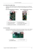
Page 67: ...Panel Figure 2 49 Physical picture of HS Signal Amplifier Panel 1 Panel card power interface 2 Signal testing interface 3 HS signal input interface 4 HS panel power outlet interface 5 HS panel power...

Page 68: ...dical syringe attached to a silicone tube Optical components that have passed tuning tests Preliminary Steps 1 Turn off the power switch on the left side of the device 2 Pull out the power cord plug f...

Page 69: ...3 Tube P21 3 Tube P4c 3 Use a 2 Ph2 Phillips screwdriver to disassemble the four M3 8 cross recessed pan head combination screws which affix the optical assembly and take off the four large D3 gasket...

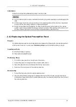
Page 70: ...orce 2 4 2 Replacing the Optical Preamplifier Panel Purpose The optical preamp panel can be disassembled and replaced by following the procedures specified in this section however in each case Prelimi...

Page 71: ...rating to avoid damaging the LED All the wirings need to be set up according to the original positions of the machine components to prevent them from being crushed or otherwise damaged 2 4 3 Replacing...

Page 72: ...the baffle plate of the laser driver panel 2 Pull out the two wires from the laser driver panel 3 Use a 2 Ph2 Phillips screwdriver to disassemble the four M3 8 cross recessed pan head combination scr...

Page 73: ...d in this section however in each case Preliminary Steps need to be taken before you begin Tools Spare Parts 2 Ph2 Phillips screwdriver Preliminary Steps Open the right side door and disassemble the t...

Page 74: ...at Step 3 5 After tuning tighten the two locking screws of the flow chamber and reinstall the cover panel of the optical system box as well as the four affixing screws then lock them in place 2 4 5 Re...

Page 75: ...angle receiving plate 2 4 6 Common Problems and Solutions Problem Description Possible Cause Solution There is no scattergram signal when testing the DIFF signal of whole blood The laser driver panel...

Page 76: ...ich are not significantly different in brightness check if the pinch valve is working if it is check if Valve 10 11 12 13 and 18 are also working The scattergram signals are basically normal but compr...

Page 77: ...put on rubber gloves and clean both hands with disinfectant after performing any repair work 3 2 Preparatory Work before Repairs 3 2 1 Disassembling the Left Side Panel Purpose While performing regula...

Page 78: ...cessed pan head combination screw 4 2 As shown in Figure 3 2 use 2 Ph2 cross screw driver to take out three M3 8 cross recessed pan head combination screws on the left side panel and take off the left...

Page 79: ...bly which are all in the right section of the machine Tools Spare Parts Slot type screwdriver Opening As shown in Figure 3 3 insert the slot type screwdriver into the slot in the right side door lock...

Page 80: ...Door Disassembly 1 Disassembly the back panel use a 2 Ph2 Phillips screwdriver to disassemble the three M3 6 cross recessed pan head combination screw on the back panel and take off the back panel as...

Page 81: ...ff the panel cover as shown in Figure 3 6 take out the six affixing M3 8 cross recessed countersunk head screws in order to take off the panel cover When removing the panel cover make sure to pull out...

Page 82: ...the LCD screen interface panel use 2 Ph2 cross screw driver to remove four M3 8 cross recessed pan head combination screws on the shield panel take off the shield panel then detach the black buckles o...

Page 83: ...embly Replacement 3 4 1 Replacing the Sample probe Purpose The sample probe can be disassembled and replaced by following the procedures specified in this section however in each case 3 2 Preparatory...

Page 84: ...s screwdriver to take out the two M3 6 small cross recessed pan head combination screws on the fixed pressure plate of the sample probe and then take off the fixed pressure plate See Figure 3 10 Figur...

Page 85: ...ch to remove the M3 hex screw affixing the optocoupler then pull out the plug attached to the optocoupler wire to disassemble the optocoupler to be replaced See Figure 3 11 Figure 3 11 Replacement of...

Page 86: ...the bracket for drag chains to detach the sampling specific drag chain from the sampling assembly See Figure 3 12 Figure 3 12 Replacement of the sampling assembly in X or Y direction 1 1 tank drag cha...

Page 87: ...ced by following the procedures specified in this section however in each case 3 2 Preparatory Work before Repairs need to be taken before you begin Tools Spare Parts Phillips screwdriver Power assemb...

Page 88: ...with screws 3 6 Hydraulics Components incl Valves Pumps and Pressure Chambers Replacement 3 6 1 Replacing the valve assembly Purpose The valve assembly can be disassembled and replaced by following th...

Page 89: ...e valve assembly and carefully take out the valve assembly while making sure to unplug the attached wires See Figure 3 15 Figure 3 15 Replacement of valve assembly 1 the corresponding replacement valv...

Page 90: ...left side of the device 2 Pull out the power cord plug from the rear panel of the device 3 Open the right side door Disassembly 1 Pull out the peripheral fluid tubes and wire connectors attached to t...

Page 91: ...ay special attention to the tubing joints and ensure that the connections are sound Follow the corresponding disassembly steps in reverse order Resetting the Machine 1 Close the right side door 2 Plug...

Page 92: ...r assembly See Figure 3 18 Figure 3 18 Replacement of negative pressure chamber assembly 1 Negative pressure chamber assembly 2 M4 10 cross recessed pan head combination screw 2 3 The further dismantl...

Page 93: ...ewdriver The replacement syringe assembly with the same specifications Preliminary Steps Open the left side door Disassembly 1 Pull out the peripheral fluid tubes connected to the syringe assembly to...

Page 94: ...Use 2 Ph2 cross screw driver to remove four M3 8 cross recessed pan head combination screws take off the syringe assembly See Figure 3 20 Figure 3 20 Replacement of motor 1 2 1 3 Use the 2 5mm hex soc...

Page 95: ...be disassembled and replaced by following the procedures specified in this section however in each case Preliminary Steps need to be taken before you begin Tools Spare Parts 2 Ph2 Phillips screwdriver...

Page 96: ...of the counting bath 2 Cross recessed pan head combination screw 2 Pull out the peripheral fluid tubes attached to the WBC counting bath assembly Pay attention to handling the residual fluid try to pr...

Page 97: ...WBC counting bath assembly Pay attention to the wiring in the process of moving to avoid breaking the wires 6 Remove the protective ring from the shield case and open the wire clip to take out the in...

Page 98: ...hine 1 Reinstall the shield case cover 2 Close the right side door 3 Plug the power cord into the back panel of the device and turn on the power switch on the left panel of the device 3 8 2 Dismantlin...

Page 99: ...to the RBC counting bath assembly Pay attention to handling the residual fluid try to prevent it from flowing onto the other components in the machine and wipe clean if necessary 3 Use a 2 Ph2 Philli...

Page 100: ...res 6 Remove the protective ring from the shield case and open the wire clip to take out the inner wire along the stretching direction of the wire Then take out the RBC counting bath assembly as a who...

Page 101: ...wer switch on the left panel of the device 3 9 Main Control Panel Replacement Purpose The main control panel can be disassembled and replaced by following the procedures specified in this section howe...

Page 102: ...ce and turn on the power switch 3 10 Reagent Testing Panel Replacement Purpose The reagent testing panel can be disassembled and replaced by following the procedures specified in this section however...

Page 103: ...n screw 2 2 Pull out all the exposed peripheral wires connected to the reagent testing panel 3 Remove the four M3 8 cross recessed pan head combination screws affixing the reagent testing panel and ca...

Page 104: ...anel of the device 3 11 Disassembling and Replacing the Temperature Sensor Purpose The temperature sensor can be disassembled and replaced by following the procedures specified in this section however...

Page 105: ...ure sensor bracket 3 M3 8 fixation screws Installation Follow the corresponding disassembly steps in reverse order Resetting the Machine 1 Re install the front panel cover and close the corresponding...

Page 106: ...mate manufacturers The USB flash disk capacity shall be larger than 1G and the format is FAT32 2 Copy the upgrade package to the root directory of the USB flash disk Do not paste it into any newly cre...

Page 107: ...cognised there will be dialog box in the interface as follows 2 Select the upgrade file upgrade_1108_vxxx_XXXXXXXXXXXX tar bz2 and click Yes vxxx indicates the version of the upgrade file and XXXXXXXX...

Page 108: ...analyser 4 3 Touch Screen Calibration After replacing with a new touch screen it is necessary to calibrate the touch screen prior to use steps for calibration are as follows 1 Prepare a USB flash disk...

Page 109: ...e a hard object such as a toothpick or pencil to click the focal points successively appearing on the screen 5 points in total After clicking 5 focal points the touch screen calibration is complete 6...

Page 110: ...sampling assembly or swab perform the following tuning procedures 1 Enter the Service screen and click Position Adjustment 2 Click Start and check the distance between the bottom of the sample probe a...

Page 111: ...setting needs to be performed for the replacement of WBC bath HGB wire and or main control panel 1 In the Setup Meterage screen click Gain Settings 2 Click the up down adjustment button after the fil...

Page 112: ...mpted to redo the calibration Please click OK to close the message box Then click Clear to delete the data and repeat step 3 4 Perform the QC test for three times in a row for the second run The resul...

Page 113: ...6 Repeat step 5 for a total of 12 times to get 12 results of calibration counting After the counting is complete a dialog box will pop up indicating that the test is complete Click the Save button to...

Page 114: ...P address and port number Refer to Description of LIS Communication Protocol for Haematology Analysersto complete the support of the LIS workstation to the LIS communication protocol 5 5 2 Host Commun...

Page 115: ...hall be the same while other parameters can maintain null 5 Click OK to save the settings and close the dialog box 5 5 3 Connecting Analyser with LIS 1 Log on the InSight V5 Haematology Analyser softw...

Page 116: ...ample real IP should be in the same network segment with LIS server 4 Click OK to save the settings 5 Check if the connection is successful The LIS icon in the upper right side on the analyser screen...

Page 117: ...pler status shown in the screen is blocked if yes then the optocoupler is working properly 2 Follow the instructions in 3 7 2 Replacing the Motor to disassemble the syringe motor and replace it with a...

Page 118: ...er to 3 4 3 Replacing the Sampling Assembly in X or Y direction to disassemble the motor from the sampling assembly and make sure motor wiring is secure If the wiring is OK then disassemble the motor...

Page 119: ...perform the following procedures 2 Go to Setup Host Settings Gain Settings screen adjust the current HGB gain and set HGB background voltage within 4 5 0 1V 3 If the problem persists please try to cl...

Page 120: ...er to 2 2 12 4 Clogging of the Flow Chamber DIFF Probe to clean the flow chamber or DIFF probe for multiple times DIFF probe clogging 11 Abnormal background Abnormal background One or multiple results...

Page 121: ...nt remaining is insufficient to support hydraulics operations such as counting Please follow the troubleshooting procedures below Go to the Reagent Management Setup screen scan the barcode of the new...

Page 122: ...bubbles in inlet tubing or is running out 2 If there is no V5 LY2 replace with new V5 LY2 Click the Remove Error button to automatically resolve the error 3 If the remaining volume of V5 LY2 is a lot...

Page 123: ...1 0125A Front panel cover 11 22 01 0018A Indicator light panel PCBA 12 22 01 0204A Reagent presence testing PCBA 13 22 01 0021C PCBA of the main control panel Programmed 1104 14 22 01 0025A Reagent se...

Page 124: ...43 37 01 0021A Grounding wire for the rear panel 44 37 02 0748A Valve control wire 1 10 1104B 45 37 02 0750A Valve control wire 11 20 1104B 46 37 02 0534A Control wire for the sampling syringe 1104B 4...

Page 125: ...1104 Keyboard plate for sample absorption switch 74 60 10 0024A 1104 series screen printing housing 75 63 01 0001A STHT tube for maintenance 76 63 01 0002A Pharmed tube for maintenance 77 63 01 0007A...

Page 126: ...7 Maintenance Inventory Copyright WOODLEY EQUIPMENT COMPANY LTD 120...

Page 127: ...7 Maintenance Inventory Copyright WOODLEY EQUIPMENT COMPANY LTD 121...

Reviews: