


33
3.3.2 RSTP BRIGDE SETTING
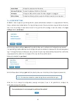
The STP mode includes the
STP
,
RSTP
and
Disable
. User can select the STP mode for user system first. The default
mode is RSTP enabled. After user selects the STP or RSTP mode; user should continue to configure the global Bridge
parameters for STP and RSTP.
Spanning Tree Protocol (STP)
STP is a Layer 2 link management protocol that provides path redundancy while preventing loops in the network. For
a Layer 2 Ethernet network to function properly, only one active path can exist between any two stations.
Spanning-tree operation is transparent to end stations, which cannot detect whether they are connected to a single
LAN segment or a switched LAN of multiple segments.
Rapid Spanning Tree Protocol (RSTP)
If the destination from a switch is more than one path, it will lead to looping condition that can generate broadcast
storms in a network. The spanning tree was created to combat the negative effects of message loops in switched
networks. A spanning tree algorithm is used to automatically sense whether a switch has more than one way to
communicate with a node. It will then select the best path, and block the other path. Spanning Tree Protocol (STP)
introduced a standard method to accomplish this. Rapid Spanning Tree Protocol (RSTP) was adopted and represents
the evolution of STP, providing much faster spanning tree convergence after a topology change.
Bridge Configuration
Bridge Address:
This shows the switch’s MAC address.
Bridge Priority (0-61440)
: RSTP uses bridge ID to determine the root bridge, the bridge with the highest bridge ID
becomes the root bridge. The bridge ID is composed of bridge priority and bridge MAC address. So that the bridge
with the highest priority becomes the highest bridge ID. If all the bridge ID has the same priority, the bridge with the
lowest MAC address will then become the root bridge.


