background image

17

3060918_1203

ComfortLine decorative panel installation

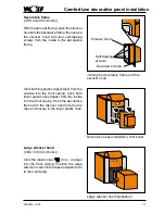
Decorative frame

(CHU 22-29 Unit boiler)

With the dome at the top, push the silencer 

hood into the decorative frame, then secure 

the silencer hood with four self-tapping 

screws from the inside to the decorative 

frame.

Self-tapping 

screws

Silencer hood

Decorative frame

Joining the decorative frame and the 

silencer hood

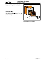
Large silencer hood installation

Large silencer hood

(CNU 37-60 Unit boiler)

Click the plastic clips 

 (4 no., orange) 

into the front casing. Position the large 

silencer hood onto the clips and push down 

to their end stop.

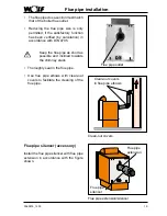
Click both top plastic clips (black) from the 

outside into the front casing. Click both 

lower plastic clips (black) from the inside 

into the front casing. Hook the decorative 

frame with the silencer hood into the top 

clips and secure in the lower plastic clips.

Decorative panel installation, Unit boiler

Summary of Contents for ComfortLine CHK

Page 1: ...ce instructions ComfortLine FunctionLine Cast iron boilers up to 60 kW GB Part No 3060918_1203 Subject to modifications Wolf GmbH Postfach 1380 84048 Mainburg Tel 49 8751 74 0 Fax 49 8751 741600 Internet www wolf heiztechnik de ...

Page 2: ...r 11 Boiler assembly 12 15 ComfortLine decorative panel installation 16 17 FunctionLine decorative panel installation 18 Flue pipe installation 19 Central heating to boiler connections 20 DHW cylinder to boiler pipework 21 Filling the heating system 22 23 Draining the heating system 24 Pressure jet oil burner installation Electrical supply 25 Initial start up 26 27 Maintenance 28 29 Maintenance lo...

Page 3: ... installation com missioning or maintenance work Adhere to the instructions given in this document Non observance of these installation instructions voids any guarantee offered WOLF Safety instructions Only use qualified and trained personnel for the installation commissioning and maintenance of the boiler In accordance with DIN EN 50110 1 work on electrical components e g control units may only b...

Page 4: ...t be observed during installation BoilerroomguidelinesorBuildingRegu lations relating to the construction and installation of central boiler rooms and fuel storage facilities EnergySavingsAct EnEG andrelated directives Heating Systems Order Note Please read these instructions carefullybeforetheinstallation andkeeptheminasecureplace DIN standards DIN 1988 Technical rules for DHW installations DIN 4...

Page 5: ...rective for heating systems with heating circuit pumps and flow temperatures up to 110 C and 3 bar permissible operating pressure in accordance with DIN 4751 and DHW cylinder pres sure max 10 bar in accordance with DIN 4753 Fortheoperationwithpressurejetgasburners thefollowinggasdevicecategoriesapply The NOx limits required by the 1st BImSchV para 7 2 are maintained Country abbreviation Country Ga...

Page 6: ...rs type CHK boiler plinth accessory Oil and gas fired cast iron boilers type CHK CB incl DHW cylinder Oil fired cast iron Unit boiler type CHU incl pressure jet oil burner boiler plinth accessory Oil firedcastironUnitboiler typeCHU CB incl DHW cylinder and pressure jet oil burner ...
Page 7: ...peFHK boiler plinth accessory Oil and gas fired cast iron boilers type FNK FB FE incl DHW cylinder Oil fired cast iron Unit boiler type FHU incl pressure jet oil burner boiler plinth accessory Oil firedcastironUnitboiler typeFHU FB FE incl DHW cylinder and pressure jet oil burner ...
Page 8: ... rising towards the back to ensure adequate venting of any trapped air level with adjustable feet Only install the boiler and DHW cylinder if installed in a room safe from the risk of frost Drain the boiler the DHW cylinder and the entire heating system if there is a risk of frost when the system has been shutdown to prevent pipes from bursting Boilers should not be installed in areas subject to a...

Page 9: ...m wall clearance Transportation into the boiler room To ease the transportation into the boiler room lifting slings with lifting hooks are offered as accessories Only lift the boiler using all four lifting slings Note Lifting eyes for lifting slings Boilerinstallationonadjustablefeet At the factory the boiler is equipped with four adjustable bolts Level the boiler with adjustable feet accessory ho...

Page 10: ...ation on a plinth Boiler Boiler door Thermal insulation boiler Thermal insulation boiler back Thermal insulation boiler front Side casing Control unit bracket Back wall casing Control unit housing Casing cover Spring shackles Front casing Type plate Wolf logo Plinth accessory ...

Page 11: ...orizontal DHW cylinder Boiler Boiler door Thermal insulation boiler Thermal insulation boiler back Thermal insulation boiler front Side casing Control unit bracket Back wall casing Control unit housing Casing cover Spring shackles Front casing Type plate Wolf logo Horizontal DHW cylinder ...

Page 12: ...ogether with the plinth and DHW cylinder and adjust with a slightinclinetotherear ifnecessary Screws for securing the boiler Screws for securing the boiler to the plinth Screws for securing the boiler Fixing screws on the DHW cylinder Position the thermal boiler insulation around the boiler overlapping and secure with spring clips Positionthethermalboilerinsula tionfortheboilerbackovertherear conn...

Page 13: ...rol unit bracket installation Locate the control unit bracket centrally and push parallel forward until both recesses in the side casing clickintothecontrolunitbrackettabs and fit the lower folded edge into both notches of the boiler view X Boiler notch Lower folded edge of the side casing View X Side casing installation Side casing intotheboilerfrontpushingthespring clip behind the boiler bracket...

Page 14: ...ied to the control unit at the l h and r h rear working from top to bottom Route the boiler sensor to the front and push into the sensor well in any arrangement then secure with the circlip Rear wall installation Back wall notches Self tapping screws Locate the back wall casing with tabs into the notches in the side casing and secure with the self tapping screws 4 no supplied Side casing fixing sc...

Page 15: ...ring shackles until they click into place Front casing installation Position the casing cover onto both side casings and push towards the control unit bracket Cable clip Cover cap Burner cable holder Guide the burner cable through the aperture in the control unit bracket l h or r h subject to boiler door opening Clip a cover cap into the control unit bracket to protect the burner cable Secure the ...

Page 16: ...decorative panel with the document wallet on the holes and push against the front casing until the clips click into place Decorative panel installation Decorative panel installation single boiler Decorative frame CHK 22 60 single boiler Click the plastic clips 4 no black into the front casing Position the decorative frame onto the clips and push down to their end stop ...

Page 17: ...ative frame and the silencer hood Large silencer hood installation Large silencer hood CNU 37 60 Unit boiler Click the plastic clips 4 no orange into the front casing Position the large silencerhoodontotheclipsandpushdown to their end stop Click both top plastic clips black from the outside into the front casing Click both lower plastic clips black from the inside into the front casing Hook the de...

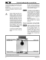
Page 18: ...ne decorative panel installation For models FHU TH 22 29 the following additional work should be undertaken Decorative panel Click the plastic clips 4 no grey into the front casing Decorative panel installation Decorative panel ...

Page 19: ...an out covers Clean out covers in flue pipe elbows Thefluepipecross sectionmustmatch that of the boiler flue outlet Reducing the flue pipe size is only permitted if the satisfactory function has been verified by calculation in accordance with DIN 4705 Keep the flue pipe as short as possible and inclined towards the chimney stack Thoroughly seal in the flue pipe Use flue pipe elbows with clean out ...

Page 20: ...urst the boiler body or the boiler pipework which would lead to a sudden excape of hot water risk of scalding Connectanyunderfloorheating system via a three or four way mixer Return temperature raising facility Heating systems with large water volume above 20 litres per kW output require a re turn temperature of 30 C as otherwise the longer heat up time of such systems would create condensate and ...

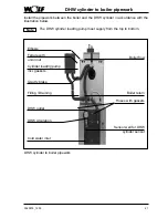
Page 21: ...stration below The DHW cylinder loading pump must supply from the top to bottom Note Boiler return Boiler flow Hoses with gaskets Sensor well for DHW cylinder sensor Cold water inlet DHW circulation DHW outlet Filling Draining Cylinder loading pump incl gaskets Ferrule with union nut Gravity brake Elbows DHW cylinder to boiler pipework ...

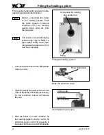
Page 22: ...ning pressure maximum 3 bar has been installed Note Note Filling the heating system Connection for venting and safety flow Filling With the boiler in a cold condition fill the heating system slowly via the fill and drain valve until 1 bar pressure is indicated Inhibitorsarenotpermissible Automatic air vent valve Locking cap Automatic air vent valve Openthecapofthequick actionair vent valveofthesaf...

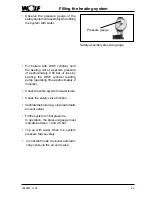
Page 23: ...of approximately 0 50 bar or less by starting the DHW cylinder loading pump operating time approximately 2 minutes Checktheentiresystemforwaterleaks Check the safety valve function Ventilatetheboiler e g viaanautomatic air vent valve Fillthesystemto1barpressure In operation the pressure gauge must indicate between 1 and 2 5 bar Top up with water when the system pressure falls severely In constant ...

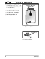
Page 24: ...Draining the heating system Connection for venting and safety flow Drain Switch OFF the heating system see operating instructions and let it cool downtoamaximumof40 C toprevent the risk of scalding Open the drain tap on the boiler Open the radiator bleed valves Drain the heating water off ...

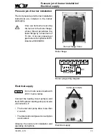
Page 25: ...eeded Observe the control unit installation and operating instructions Note Electrical supply Cable grommets Pressure jet oil burner installation The Unit pressure jet oil burner installation instructions are included in the burner packaging Only use bolts when securing the burner to the boiler flange whose thread penetrates the boiler flange by a maximum of 15 mm Only use pressure jet gas burners...

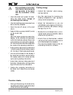
Page 26: ...ler burner fails to start properly For details about error codes see the quick start operating instructions Instructthecustomerin theoperationof theboiler Completethecommissioning log and hand over the instructions Position the operating instructions in the boiler room where they are clearly visible Saving energy Instruct the customer about energy savings options Use this opportunity for reducing ...

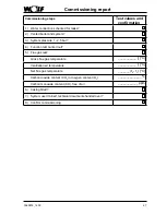
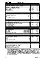
Page 27: ... System pressure 1 2 5 bar 4 Function test carried out 5 Flue gas test Gross flue gas temperature tA C Ventilation air temperature tL C Net flue gas temperature tA tL C Carbon dioxide content CO2 or oxygen content O2 Carbon monoxide content CO free of air ppm 6 Casing fitted 7 System user trained technical documents handed over 8 Confirm commissioning ...

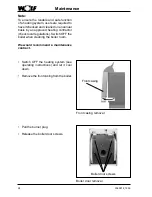
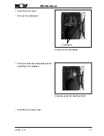
Page 28: ...heating contractor check local regulations Switch OFF the boiler when cleaning the boiler room We would recommend a maintenance contract Front casing Front casing removal Switch OFF the heating system see operating instructions and let it cool down Remove the front casing from the boiler Pull the burner plug Release the boiler door screws Boiler door screws Boiler door removal ...

Page 29: ...aintenance Turbulators Pulling out the turbulators Open the boiler door Pull out the turbulators Cleaning using the cleaning brush Remove soot sulphur deposits with the cleaning brush supplied Assemble in reverse order ...

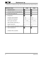
Page 30: ...ion test carried out 4 Flue gas test Gross flue gas temperature tA C _________ tA C _________ Ventilation air temperature tL C _________ tL C _________ Net flue gas temperature tA tL C _____ tA tL C _____ Carbon dioxide content CO2 or ____________ ____________ Oxygen content O2 ____________ ____________ Carbon monoxide content CO free of air ppm__________ ppm__________ 5 Confirm maintenance compan...

Page 31: ...___ tA C _________ tL C _________ tL C _________ tL C _________ tL C _________ tA tL C _____ tA tL C _____ tA tL C _____ tA tL C _____ ____________ ____________ ____________ ____________ ____________ ____________ ____________ ____________ ppm__________ ppm__________ ppm__________ ppm__________ ...

Page 32: ... h 540 540 Performance factorCB FB NL60 2 8 4 4 FE NL60 2 8 4 1 Number of boiler sections 3 3 Water content litres 29 29 Boiler gas content litres 33 33 Heating water pressure drop at T 20K mbar 2 2 Maximum permissible boiler pressure bar 4 4 Maximum permissible DHW cylinder pressure bar 10 10 Rel standby losses Boiler 1 15 1 15 Boiler DHW cylinder 1 7 1 9 Required boiler draught Pa 10 10 Flue gas...

Page 33: ...4 5 4 5 4 4 5 6 8 35 35 41 47 59 43 43 53 63 83 4 4 6 8 14 4 4 4 4 4 10 10 10 10 10 1 05 1 05 0 95 0 85 0 7 1 6 1 8 1 6 1 4 1 2 13 13 16 19 0 140 170 140 170 150 170 150 170 155 175 37 49 37 49 49 62 62 75 80 100 1 1 1 1 1 1 1 1 1 1 129 129 149 149 149 450 450 550 650 850 290 290 290 290 290 198 198 229 260 322 10 10 15 5 15 5 15 5 66 83 83 83 83 98 121 121 121 121 230 V 50 Hz 10A 5 VA 15 VA 230 V...

Page 34: ...35 835 Width B mm 660 660 660 660 660 Length C mm 640 740 840 940 1040 Plinth height D mm 280 280 280 280 280 Overall height incl control unit E mm 1280 1280 1280 1280 1280 Silencer hood depth F1 mm 336 336 345 345 345 Burner hood depth F2 mm 235 235 235 260 275 Central heating return G mm 397 397 397 397 397 Smoke tube connector H mm 859 859 859 859 859 Central heating flow J mm 997 997 997 997 9...

Page 35: ...r C mm 1262 1262 1262 1262 1262 DHW cylinder height D mm 625 625 625 625 625 Overall height incl control unit E mm 1625 1625 1625 1625 1625 Silencer hood depth F1 mm 336 336 345 345 345 Burner hood depth F2 mm 235 235 235 260 275 Central heating return G mm 742 742 742 742 742 Smoke tube connector H mm 1204 1204 1204 1204 1204 Central heating flow J mm 1342 1342 1342 1342 1342 Cold water inlet K m...

Page 36: ...ng circuit pump Cylinder loading pump does not run DHW cylinder thermostat faulty Check DHW cylinder thermo stat and replace if necessary Cylinder loading pump seized up Turn the pump shaft with a screwdriver Cylinder loading pump faulty Replace the DHW loading pump Heating system operational but room temperature too low Adjust maximum boiler tem perature set too low Raise maximum boiler tem perat...

Reviews: