background image

6


[Assembling Steps] 


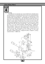
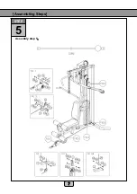
Assembly step 4


Mount Backrest 30 on adjustable tube 3 using 2X(53) M8*25-Bolt

2X(63)Φ8-Washer.   

Insert adjustable tube 3 into Adjusting bushing 4 and secure with T-shaped adjustable pin 
40. (Note: Tight the Nut to threaded pipe).    Mount Seat 31 on adjustable tube 10 using   
2X(53) M8*25-Bolt

2X(63)Φ8-Washer.    Insert adjustable tube 10 into Seat frame 12 and 

secure with T-shaped adjustable pin 40.( Note: Tight the Nut to threaded pipe). Slide Leg 
kicking  tube  11  into  Leg  kicking  adjustable  tube  20  and  then  from  each  side,  insert 
assembly  of  Plastic  bushing  77,Sponge  tube  37  and  secure  with  Plastic  bracket  76.   
Insert Leg kicking adjustable square tube 20 into Seat frame 12 and secure with T-shaped 
adjustable pin 40.(Note: Tight the Nut to threaded pipe).    Attach Leg kicking frame 24 to 
Seat  frame  12  by  using  1X(49)  M12*80-Bolt

2X(66)Φ12-Washer

1X(69)M12-Nut.   

Attach  Connecting  cover  21  to  Leg  kicking  frame  24  using  1X(48)  (M12*75)-Bolt

2X(66)Φ12-Washer

1X(69)M12-Nut

Slide Leg kicking tube 11 into Connecting cover 21 

and  then  from  each  side,  insert  assembly  of  Plastic  bushing  77,Sponge  tube  37  and 
secure  with  Plastic  bracket  76.Attach  hook  25  to  seat  frame  12  using  1X(61) 
M10*90-Bolt

2X(65)Φ10-Big Washer

1X(46A)Φ14*6-bushing

1X(45)Φ14*11- bushing

1X(64)Φ10-Washer

1X(68)M10-Nut.


6

STEP 

Summary of Contents for F1-518CIt

Page 1: ...1 1 Index Page 1 1 Important statement 2 Admonition 3 Assembling Steps 4 Exploded View 5 Parts list 6 Exercise Descriptions 7 Notice items 8 Daily Maintain 2 2 3 8 9 10 11 12 14 15 15...

Page 2: ...ne the faulty operation will bring yourself and the other people huge harm we have used the words of warning attention on the faulty manipulating Every step on operation is concern to the safety pleas...

Page 3: ...and Back tube 13 by 2X 59 M10 75 Bolt 4X 64 10 Washer 2X 68 M10 Nut Attach Support tube 14 to Seat frame 12 by using 2X 59 M10 75 Bolt 4X 64 10 Washer 2X 68 M10 Nut Attach Adjusting bushing 4 to Suppo...

Page 4: ...ward and insert Leader 9 into holes of Base tube 8 Slide each Weight stack 33 into Leader 9 Insert Steeve 6 in slot under top plate of Weight stack 33 Insert Briquetting 34 to Leader 6 and secure usin...

Page 5: ...Washer 2X 68 M10 Nut Attach Handspike 18 on each side to Chest press frame 17 using 1X 59 M10 75 Bolt 2X 64 10 Washer 1X 68 M10 Nut Attach Fixed tube nip 39 on each side Chest press frame 17 using 1X...

Page 6: ...y of Plastic bushing 77 Sponge tube 37 and secure with Plastic bracket 76 Insert Leg kicking adjustable square tube 20 into Seat frame 12 and secure with T shaped adjustable pin 40 Note Tight the Nut...

Page 7: ...1 7 Assembling Steps Assembly step 5 7 STEP 5...

Page 8: ...1 8 Assembling Steps Assembly step 6 8 STEP 6...

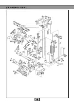
Page 9: ...1 9 EXPLODED VIEW 9...

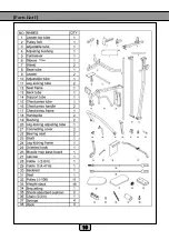
Page 10: ...1 10 Parts List I 10...

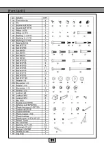
Page 11: ...1 11 Parts List II 11...

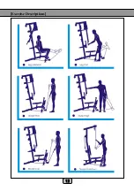
Page 12: ...1 12 Exercise Descriptions 12...

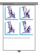
Page 13: ...1 13 Exercise Descriptions 13...

Page 14: ...1 14 Exercise Descriptions 14 Note This equipment can do many sports the above is only part of them...

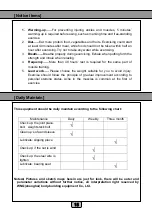
Page 15: ...of muscle training 5 Load work Please choose the weight suitable for you to avoid injury Exercise should follow the principle of gradual improvement according to personal stamina status Ache in the mu...

Reviews: