background image

62 
 

3.5 Storage Management 

3.5.1 Schedule 

Before schedule setup, user must set record mode in record control as auto status. 

Note

: If record mode in record control is off, then device will not record or snapshot according to the schedule. 

3.5.1.1 Record Schedule 

Step 1

,


Select “Setup > Storage > Schedule > Record Schedule”. 
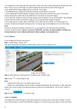
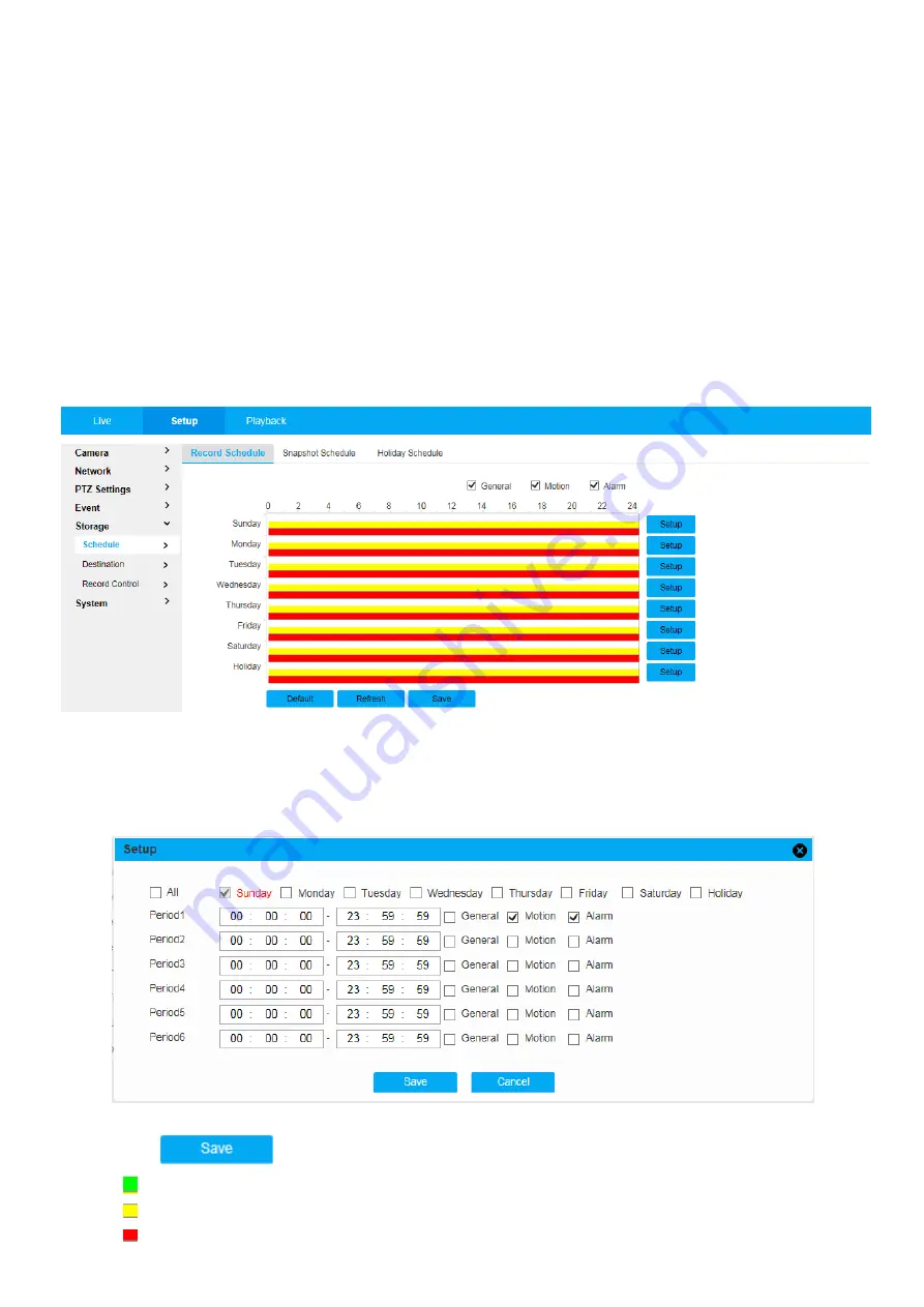
The system will display the interface of “Record Schedule”, which is shown in Figure 3.5-1. 


Figure 3.5-1 Record Schedule 

Step 2

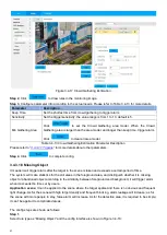
From Monday to Sunday select record time, click “Setup” on the right. See Figure 3.5-2 for more details. 


● Set period according to actual needs. There are six periods available each day. 


● By checking or cancel, you can add or delete three types of record schedule: General, Motion, and Alarm. 

Note

: Period setup can be done by dragging in record schedule interface while not releasing left mouse. 


Figure 3.5-2 Record Schedule Time Setup 

Step 3

, Click 

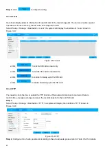
, return to record schedule interface. See Figure 3.5-3. 


Green color stands for the general record. 


Yellow color stands for the motion detect record. 


Red color stands for the alarm record. 

Summary of Contents for ON-IPD699TS-30X-2M

Page 1: ...I Block Zoom Camera User s Manual V1 0 1...

Page 2: ...nterface Operation Description For the specific type of appearance and interface please refer to the specification datasheet detail The content is subject to change without notice The updates will be...

Page 3: ...7 2 4 PTZ Config 7 2 4 1 PTZ Control 7 2 4 2 PTZ Setting 8 2 4 3 PTZ Menu 9 3 Setup 10 3 1 Camera 10 3 1 1 Conditions 10 3 1 1 1 Picture 10 3 1 1 2 Exposure 11 3 1 1 3 Backlight 13 3 1 1 4 White Bala...

Page 4: ...40 3 3 2 8 PowerUp 40 3 3 2 9 PTZ Limit 41 3 3 2 10 Time Task 42 3 3 2 11 PTZ Restart 42 3 3 2 12 Default 43 3 4 Event Settings 44 3 4 1 General Event 44 3 4 1 1 Motion Detection 44 3 4 1 2 Audio Det...

Page 5: ...3 6 1 3 Date Time 68 3 6 2 Account 69 3 6 2 1 Account 69 3 6 2 2 Online User 72 3 6 3 Maintain 72 3 6 3 1 Log 72 3 6 3 2 Default 73 3 6 3 3 Upgrade 74 4 Playback 75 4 1 Video Playback 75 4 1 1 Play F...

Page 6: ...4PIN Internet Interface 1 ETHRX Internet RX 2 ETHRX Internet RX 3 ETHTX Internet TX 4 ETHTX Internet TX 2 6PIN Power COM Interface 1 DC_IN DC IN DC 9V 12V 2 GND GND 3 RXD2 RS232 RXD TTL3 3V Pelco Pro...

Page 7: ...ernet cable 3 Tail Board Connection Connect the Tail board and the block zoom camera with 4PIN cable and 6PIN cable Figure 3 1 Connect the DC 12V power adapter and the Ethernet cable to the Tail board...

Page 8: ...1 1 1 Direct Connection Figure 1 1 2 Connection with Switch For convenience we say it to Camera for Block Zoom Camera Default IP address 192 168 1 108 Default User Name admin Default Password admin 1...

Page 9: ...t the 1st time Please click button to install The ActiveX installer is Please Double Click it to install Figure 1 2 2 ActiveX Control Installing Step2 Input the default Usernames admin and default pas...

Page 10: ...put the New Password and Confirm Password then Click to login Or click button to skip to login Figure 1 2 3 Modify Password It will show as below after login successfully Figure 1 2 4 Figure 1 2 4 Web...

Page 11: ...Window Function Menu 4 PTZ config column Table 2 1 Menu Description 2 1 System Menu Click System menu button to goto each system interface Figure 2 1 1 System Menu 2 2 Video Window Adjustment Menu Fig...

Page 12: ...m in the selected area to large window It can drag the picture to adjust the Zoom In area position and Scroll mouse to adjust the digital zoom time Right click mouse to go back to default preview Snap...

Page 13: ...ea on the preview 3 Speed Set the Pan Tilt Speed Total 8 level 1 is lowliest 8 is fastest 4 Zoom Focus Iris Click and to control the Zoom Focus Iris value 5 Light Wiper Lens Init Click to Turn ON OFF...

Page 14: ...The Aux Number depends on the PTZ protocol Pan Pan Scan Select Pan from the dropdown list and then click Start button and it can realize horizontal rotation of the PTZ Go To Accurate positioning Inpu...

Page 15: ...t standard or vivid It is standard by default Brightness Set the overall brightness of image the bigger the value is the brighter the image becomes Range 0 to 100 Contrast Set the image contrast the b...

Page 16: ...change the direction of video surveillance image It can select normal and flip It is normal by default EIS It can realize EIS function via image difference value comparison algorithm which can effecti...

Page 17: ...12 Figure 3 1 4 Exposure Shutter Priority Figure 3 1 5 Exposure Gain Priority Figure 3 1 6 Exposure Manual Step 2 Configure parameter info according to actual needs see Table 3 1 2...

Page 18: ...l exposure mode it can manually adjust gain value and shutter value it supports long exposure Gain Range Set the gain value of exposure Range 0 to 100 Shutter Adjust shutter time The bigger the shutte...

Page 19: ...ce in dark environment and realize quite good effect of license plate details WDR Enable WDR to suppress the over bright area and compensate over dark area which can make the whole image a quite clear...

Page 20: ...witch Electrical It uses image processing mode for day night switch Mode Set image color and B W mode which is not influenced by the selection of config profile It is Auto Mode by default Color The ca...

Page 21: ...r than Auto Focus Limit Set the nearest distance of focus and focus on the object beyond the distance the auto option will make it select proper nearest distance automatically according to the differe...

Page 22: ...t is Middle by default Step 3 Click to complete config 3 1 1 8 Profile Management It can select three modes of profile management such as normal full time and schedule When it selects Normal the video...

Page 23: ...snapshot overlay ROI and path 3 1 2 1 Video It is to set video stream of the monitoring image The config steps are shown as follows Step 1 Select Setup Camera Encode Video The system displays the inte...

Page 24: ...value can provide best reference range I Frame Interval Here you can set the P frame amount between two I frames the range varies according to the frame rate the max is 150 it is recommended to set tw...

Page 25: ...shot Parameter Step 3 Click to complete config 3 1 2 3 Overlay It is to set the info which is to be overlaid on the monitoring image The config steps are shown as follows Step 1 Select Setup Camera En...

Page 26: ...21 Figure 3 1 19 Overlay OSD Information Figure 3 1 20 Overlay Picture Figure 3 1 21 Overlay Abnormal...

Page 27: ...on t display You can adjust OSD info via dragging OSD Info box Alignment include align left and align right Picture Overlay You can enable this function to display overlay picture Click disable to tur...

Page 28: ...ton to delete corresponding area Click Remove all to remove all the areas Step 4 Set the image quality of the corresponding ROI Step 5 Click to complete config 3 1 2 5 Audio It is to set the audio par...

Page 29: ...00 Speaker Volume Adjust the volume of the speaker Range from 0 to 100 Table 3 1 8 Audio Parameter Description Step 3 Click to complete config 3 2 Network 3 2 1 General 3 2 1 1 TCP IP You need to conf...

Page 30: ...IP address of DNS server Enable ARP Ping to set device IP address service Check you can use ARP Ping command to modify or set the device IP address if you know the device MAC address When it is enabl...

Page 31: ...Parameter Description 1 Click Save after filling in the interface 2 Input domain name in the PC browser and press Enter button It means successful config if it can display the device WEB interface it...

Page 32: ...User uses VLC can play the following formats Real time monitoring URL format please require real time RTSP media server require channel no bit stream type in URL You may need username and password UR...

Page 33: ...erface Please click OK to begin installation The operation steps of UPnP config is shown as follows Step 1 Select Setup Network General UPnP The system will display the interface of UPnP which is show...

Page 34: ...only when the device IP and PC s IP are in the same LAN Step 1 Select Setup Network General IP Filter The system will display the interface of IP Filter which is shown in Figure 3 2 7 Figure 3 2 7 IP...

Page 35: ...service setting It can gain the relevant config info after connecting to device via relevant software tool It needs to satisfy the following conditions if it is to use SNMP function Install SNMP devi...

Page 36: ...g port of the proxy program of the device It is a UDP port not a TCP port The value ranges from 1 to 65535 The default value is 161 Community It is a string as command between management and proxy def...

Page 37: ...assword and the sender information User Name The user name of the sender email account Password The password of sender email account Sender Sender email address Authentication Encryption mode You can...

Page 38: ...e refer to the following sheet for detailed information Table 3 2 7 Parameter Description Realtime monitor Data packet of network video monitoring the value ranges from 0 to 63 Command Configure or in...

Page 39: ...red by users Step 1 Select Setup Network Advance Bonjour The system will display the interface of Bonjour which is shown in Figure 3 2 13 Figure 3 2 13 Bonjour Step 2 Check Enable to set server name S...

Page 40: ...2 Configure info of each parameter according to the actual needs refer to Table 3 3 1 for more details Parameter Description Protocol Set PTZ protocol support PELCOD PELCOP SHINWOO Hitachi Address Se...

Page 41: ...s size adjust the camera to a proper monitoring location Step 3 Click It will add the location as preset in the list and it will be displayed in the preset list Step 4 Click save button to save the pr...

Page 42: ...he Tour Double click Tour Name to modify the name of the tour Double click Duration to set duration for each preset Step 6 Click to start tour Note The device will stop tour if PTZ is operated during...

Page 43: ...device such as pan tilt zoom call preset and etc You can directly call the pattern after it is saved completely Step 1 Select Setup PTZ Settings Function Pattern The system will display the interface...

Page 44: ...speed bar and set Pan Speed Step 3 Click to make the PTZ rotate horizontally with the speed you just set Step 4 Click to stop pan 3 3 2 6 PTZ Speed PTZ speed means the rotation speed of the device Ste...

Page 45: ...The system will display the interface of Idle Motion which is shown in Figure 3 3 8 Figure 3 3 8 Idle Motion Step 2 Check Enable to enable idle motion function Step 3 Select types of idle motion whic...

Page 46: ...hen selecting Auto Step 4 Select the number of action type Step 5 Click to complete config 3 3 2 9 PTZ Limit PTZ limit function is used to set the movement area of the device which makes the device mo...

Page 47: ...number of time task Click to delete all the time tasks which have been set Step 4 Select time take action you can select preset tour scan or pattern Step 5 Select action number Step 6 Set the time of...

Page 48: ...system will restart PTZ 3 3 2 12 Default The function can recover default settings of the PTZ The config steps are shown as follows Step 1 Select Setup PTZ Settings Function Default The system will d...

Page 49: ...iod in Storage Schedule and select auto record in record control interface Record Delay System can delay the record for specified time after alarm ended The value ranges from 10s to 300s Send Email If...

Page 50: ...select the whole week it means setting can be applied to the whole week users can also select the check box in front of the day to make separate setting for some days 4 Click button after setup return...

Page 51: ...The recommenced value is 1 10 Waveform Red means motion detection is triggered Green means motion detection is not triggered Clear all areas Delete selected area Table 3 4 2 Area Setting Description S...

Page 52: ...mplete config 3 4 1 3 SD Card Event It will trigger alarm when SD card is abnormal Step 1 Select Setup Event General Event SD Card The system will display the interface of SD Card which is shown from...

Page 53: ...erate illegal access alarm Step 1 Select Setup Event General Event Illegal Access The system will display the interface of Illegal Access which is shown in Figure 3 4 7 Figure 3 4 7 Illegal Access Ste...

Page 54: ...ep 2 Select preset in the Add Plan The system will display corresponding plan of the preset Then enable corresponding intelligent functions according to the requirements Shown in Figure 3 4 9 Figure 3...

Page 55: ...ect light Note It needs to set preset in advance please refer to 3 3 2 1 Preset for more details about preset setting There are total 9 IVS Rules Tripwire Cross Fence Detection Intrusion Abandoned Obj...

Page 56: ...You can input time number value or press the left mouse button and drag on the setting interface directly There are totally six periods to set every day click the check box in front of the period and...

Page 57: ...o warning lines Note It cannot support transparent fence such as an iron fence It cannot support too low fence Which is lower than human height Application scene There are two alarms for crossing fenc...

Page 58: ...t considering whether the target is the same or not As for the report interval of the in area function the system can detect if the same event will occur within the interval after triggering the first...

Page 59: ...ay for people via extending alarm time Application scene It can be applied to the scene where the target sparse and there is no obvious and frequent light change As for the scene with high target dens...

Page 60: ...p 1 Select rule type as Fast Moving and the config interface is shown in Figure 3 4 15 Figure 3 4 15 Fast Moving Step 2 Click to draw rules in the monitoring image Step 3 Configure parameter info acco...

Page 61: ...3 1 7 Crowd Gathering Estimation Crowd Gathering is mainly for outdoor plaza government gate station entrance and other areas When the crowd is in detention or the crowd density is too large trigger...

Page 62: ...to complete config 3 4 3 1 8 Missing Object It means it will trigger alarm after the target in the scene is taken and exceeds a certain period of time The system will make statistics for the still ar...

Page 63: ...alarm Table 3 4 14 Missing Object Parameter Description Please refer to 3 4 3 1 1 Tripwire for more details about other parameters Step 4 Click to complete config 3 4 3 1 9 Loitering Detection When t...

Page 64: ...properties and External Parameters The 3D position and direction of the camera relative to the actual environmental coordinate system of the camera and then determine the corresponding relationship b...

Page 65: ...Select the Verification type Weight Verification and Height Verification then click drag to draw a line in the video it will show the actual length beside the line When the ruler is completed it need...

Page 66: ...higher Leakage rate is the higher false detection rate is Table 3 4 16 Global Setup Parameter Description Step 9 Click to complete config 3 4 4 Advance Event 3 4 4 5 Face Detection It needs to add pre...

Page 67: ...le Step 2 From Monday to Sunday select record time click Setup on the right See Figure 3 5 2 for more details Set period according to actual needs There are six periods available each day By checking...

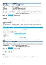
Page 68: ...of Snapshot Schedule which is shown in Figure 3 5 4 Figure 3 5 4 Snapshot Schedule Step 2 Set the snapshot period according to step 2 and 3 of 3 5 1 1 Record Schedule Step 3 Click and the system will...

Page 69: ...e are three options Local SD Card FTP and NAS You can only select one mode System can save according to the event types It is corresponding to the three modes general motion alarm in the schedule inte...

Page 70: ...rd as read only Click to set the SD card as read write Click to realize hot swap upon the SD card Click to realize formatting upon the SD card 3 5 2 3 FTP You need to check the box to enable the FTP f...

Page 71: ...can be enabled You can store file to NAS server when selecting NAS storage Step 1 Select Setup Storage Destination NAS the system will display the interface of NAS shown in Figure 3 5 9 Figure 3 5 9...

Page 72: ...the preceding n seconds video data into the record file Disk Full There are two options stop recording or overwrite the previous files when HDD is full Stop Current working HDD is overwriting or curre...

Page 73: ...hich can set the storage path of playback snapshot record download and playback clip respectively Step 1 Select Setup System General Path The system will display the interface of Storage Path which is...

Page 74: ...logged in user cannot change his her own right There is one default user admin during initialization Admin belongs to high right user by default when it is out of factory 3 6 2 1 1 User Name You can e...

Page 75: ...right user admin can t be deleted by default Step 1 Click and the system will pop out the interface of Add User which is shown in Figure 3 6 5 Figure 3 6 5 Add User Step 2 Enter user name and passwor...

Page 76: ...ick to complete config Modify password Step 1 Select the check box of Modify Password Step 2 Input old password input new password and confirm it Step 3 Click to complete config Modify password Click...

Page 77: ...2 Online User You can check the user info on the current WEB in Setup System Account Online User see Figure 3 6 8 for more details Figure 3 6 8 Online User 3 6 3 Maintain 3 6 3 1 Log In Setup System...

Page 78: ...nfig operation It includes save config delete config file Data operation It includes setting hardware type clearing data hot swap FTP status record mode Event operation it is to record the events such...

Page 79: ...tep 2 Configure the info of each parameter according to the actual needs please refer to Table 3 6 4 for more details Parameter Description Auto Reboot Check it and set auto reboot time Auto Delete Ol...

Page 80: ...torage Management before implementing playback operation Click Playback item and the system will display Playback interface which is shown in Figure 4 1 Figure 4 1 Playback 4 1 Video Playback Select f...

Page 81: ...Next frame Click this button to go to next frame Note You shall pause playback when you use this function 4 Slow Click this button to play slowly 5 Fast Click this button to play fast 6 Mute When thi...

Page 82: ...out parameters Figure 4 1 5 Playback File 1 Parameter Description File Type Select mp4 and it means record video playback Select jpg and it means picture playback Data Source It is SD card by default...

Page 83: ...tton and download file to set path Click Back button to go back to calendar interface then you can select time again to operate Table 4 1 5 Playback File Description 2 4 1 5 Progress Bar Time Format I...

Page 84: ...79 5 Logout Click button system goes back to Login interface See Figure 5 1 Figure 5 1 Logout...

Reviews: