July 2013
4222618•A
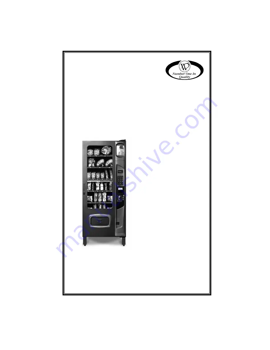
STAND ALONE COLD/FROZEN
FOOD VENDOR
(GVC2 Controller)
MODELS:
3576M/3576MA – MULT-ZONE
(Cold and Frozen Food) 3576F/3576FA – SINGLE-ZONE
(Frozen Food) 3576C/3576CA – SINGLE-ZONE
(Cold Food)
SERVICE
MANUAL
Page 1: ... 2013 4222618 A STAND ALONE COLD FROZEN FOOD VENDOR GVC2 Controller MODELS 3576M 3576MA MULT ZONE Cold and Frozen Food 3576F 3576FA SINGLE ZONE Frozen Food 3576C 3576CA SINGLE ZONE Cold Food SERVICE MANUAL ...
Page 2: ...ULTI ZONE MODE 35 CONVERTING FROM MULTI ZONE MODE TO SINGLE ZONE 35 REPLACE AIR FILTER 36 PARTS ORDERING PROCEDURE 38 BEFORE CALLING FOR SERVICE38 Please have the model and serial numbers if you need service and parts information The numbers are on the identification plate located on the back side of the cabinet of the vending machine If you have any questions pertaining to information in the manu...
Page 3: ...3 ...
Page 4: ......
Page 5: ...ls through the air duct and is deflected into the bottom zone by a moveable air deflector There are openings in the bottom trays to allow air to circulate around the products All programming of the pricing vend functions and features are also done at the controller Changes can be made without any additional accessories or remote parts Selections can be priced individually from 00 00 to 655 35 in f...
Page 6: ...0 VAC CYCLE 60 Hz 50 Hz NOMINAL AMPS 9 0 Amps 4 5 Amps TRANSFORMER 110 24 VAC 230 24 VAC REFRIGERATION HORSEPOWER EMBRACO TYPE Hermetically Sealed CONTROLS Electronic REFRIGERANT R 404a CHARGE 17 oz 482g COIN CHANGER BILL VALIDATOR CARD READER TYPE MDB Coin Changer level II or III Bill Validator Level I Card Reader Level I or II VENDOR OPERATION LOCATION Suitable for indoor use only This appliance...
Page 7: ...terial so as not to damage the finish or exterior of the vending machine Inspect the vending machine for concealed shipping damage Report any damage hidden by the shipping material directly to the delivering carrier on a hidden damage report Record the model number and serial number of the vendor for your records These numbers can be found on the Serial Plate on the rear of the cabinet and or insi...
Page 8: ...peration no further than nine feet from the power outlet or receptacle Check that the door will open fully without interference Leave at least four 6 inches of space between the back of the vending machine and any wall or obstruction for proper air circulation Figure 2 Power Cord LEVEL THE VENDOR All levelers must touch the floor The vendor must be level for proper operation cabinet to door alignm...
Page 9: ...ot skip a space Place the product on the bottom of the compartment on the product augers with the label facing the front of the vending machine for easy identification by the customer See Figure SNACK CANDY FOOD TRAY OPTION To load products lift the tray slightly and pull forward until the tray stops The trays tilt for easier loading The size of the item being vended must be larger than the diamet...
Page 10: ...g the height in one area the same amount of room will be lost at the tray above or below the one being adjusted 3 WIDE SNACK CANDY FOOD TRAY 1 Pull out the tray to be adjusted until it stops 2 Disengage the tray harness from its harness retainer on the right side wall See Figure 5a on page 7 Disconnect the tray plug from its receptacle on the right side wall 3 Lift up on the rear of the tray and r...
Page 11: ...d remove it from the vendor 7 Relocate both left and right tray rails from the left and right side walls 8 Remove tray rail mounting screws 9 Pull each rail forward to disengage its rear tab from the hole in the rear wall See Figure 5b 10 Relocate both left and right rails by reversing step 7 Rails must be level front to back and left to right 11 Replace the tray by placing its rear rollers on the...
Page 12: ...e product vends correctly Figure 5f Motor Auger Standard Tray Loading Coin Mechanism The Coin Mechanism must be loaded with some level of each coin in order for the vendor to operate properly The coins need to be loaded into the coin mechanism by insertion into the front coin insert First enter the SERVICE MODE then TUBE FILL MODE See SERVICE MODE instructions COIN TUBE FILL MODE Each tube should ...
Page 13: ...n be pressed to stop the Delivery Lift operation if necessary Information on Service Mode Configuration menu and Diagnostic Mode menu options are listed on the following pages SALES MODE When a product is selected and vended the product drops into the Delivery Lift Box after it first passes by the iVend sensor to confirm that a product has been vended Next when the machine is using the default BUT...
Page 14: ...y tray count Service Mode 4 Configuration The Delivery Lift feature can be set to 1 Button Mode The Delivery Lift Button will need to be pressed to activate the Lift 2 Automatic Mode The lift will run after each vend 3 OFF Service Mode 0 Diagnostics Contains functions for testing the Automatic Deliver Lift Door Delivery Lift and Delivery Lift Sensors See the Basic Programming pages starting on pag...
Page 15: ...ll pause for 1 second while the controller continues to monitor the optical sensor for product delivery o If a product is detected during this pause then the vend is considered successful o If a product is not detected then the controller initiates a second vend cycle and another vend timeout timer while continuing to monitor the optical sensor If a product is detected during this second cycle the...
Page 16: ... To enter Service Mode press the Service Mode Button located on the top or upper right corner of the controller cover See To exit Service Mode press the Service Mode Button NOTES If credit exists when Service Mode is entered it will be restored when the machine returns to Sales Mode If no key is pressed for approximately 1 minute while in Service Mode the controller will automatically return to Sa...
Page 17: ... in the coin mech tubes TUBE FILL STEP DISPLAY 1 Press Service Mode Button Motor Count 60 2 Press and begin depositing coins At least 15 of each denomination 3 Press 2 times to exit Sales Mode TUBE DISPENSE 1 Press to dispense dollar coin or highest denomination 1 00 coins 2 Press to dispense quarters or next highest denomination 0 25 coins 3 Press to dispense dimes or next highest denomination 0 ...
Page 18: ...4215507 for more information 3 8 SETPOINT The following are the factory default SET POINT temperature settings for each machine type MACHINE TYPE TEMPERATURE SETTINGS Frozen Slackened Cold Chilled Snack Dual Zone Dual Upper 6 NOT USED Multi Zone Food MZF Bottom Zone 10F 23C Top Zone 36F 2C Multi Zone Food 2 MZF 2 Bottom Zone 12F 24C Top Zone 36F 2C Multi Zone Food 5 MZF 5 Bottom Zone 15F 26C Top Z...
Page 19: ...E See GVC2 Programming Manual P N 4215507 for more information 4 4 LANGUAGE See GVC2 Programming Manual P N 4215507 for more information 4 5 AUTO REINSTATE See GVC2 Programming Manual P N 4215507 for more information 4 6 SPACE TO SALES STS See GVC2 Programming Manual P N 4215507 for more information 4 7 CUSTOM STS See GVC2 Programming Manual P N 4215507 for more information 4 8 TIME DATE Sets the ...
Page 20: ...h safety requirements can also be applied to an individual Item s Row s or ALL whole machine If the health safety requirements are violated then the Item s Row s or the whole machine is shut down accordingly HEALTH SAFETY ZONES Health Safety settings are split into two zones Upper Zone and Lower Zone Only the Lower Zone setting will be used when the machine is configured as a Cold Cold Food Single...
Page 21: ...Press to edit HS Zone ON OFF Enable Current Setting exit 9 edit 10 Press to toggle HS Zone ON OFF Enable Choice Flashing exit save 11 Press to save the setting Enable New Setting exit 9 edit 12 Press to exit back to main HS menu Health Safety 13 Repeat steps 4 thru 12 for another Zone or go to step 14 14 Press five times to exit Sales Mode 4 0 ADVANCED CONFIGURATION NOTE THIS IS PASSWORD PROTECTED...
Page 22: ...bly To purchase a door switch assembly please contact Vendnet Parts by phone at 1 800 833 4411 STEP DISPLAY 1 Press Service Mode Button Motors 2 Press Configuration 3 Press Password 4 Enter Password default 2314 5 Press to edit Refrigeration Type Default is Snack FROZEN Not used Dual Zone Not used Dual Upper 6 Not used Chilled Not used MZF Multi zone 10F 36F MZF 2 Multi zone 12F 36F MZF 5 Multi zo...
Page 23: ...lue button to raise the lift after each vend Auto lift will raise after each vend Off turns the lift off Auto Lift Choice Flashing exit save 8 Press to save the setting Auto Lift New Setting exit 2 edit 9 Press five times to exit Sales Mode 4 0 0 3 TOUCH COMM See GVC2 Programming Manual P N 4215507 for more information 4 0 0 4 AUTO SERVICE See GVC2 Programming Manual P N 4215507 for more informati...
Page 24: ...rice ALL Items 0 50 4 Press to save ALL Itmes 0 50 5 Press 3 times to exit Sales Mode 5 2 ROW Use this menu to set the price of a row shelf all at the same time Time Saving Suggestion Instead of setting the price of one item at a time set the common price of a Row then go back and set the price of each item STEP DISPLAY 1 Press Service Mode Button Motors 2 Press Pricing 3 Press Row 0 00 4 Enter ro...
Page 25: ...for more information 8 TEST VEND SINGLE MOTOR Use this menu to test vend individual motors The selection will display with the test vend If a test vend attempt on a particular motor fails controller will beep STEP DISPLAY 1 Press Service Mode Button Motors 2 Press Item 3 Press selection number on keypad and wait Item 010 4 Repeat step 3 for other selections 5 Press 3 times to exit Sales Mode 9 TES...
Page 26: ...peration of the individual relay lines 1 through 6 See GVC2 Programming Manual P N 4215507 for more information 0 3 LOG Engineering download for service technician ONLY 0 4 COIN REJECT RATE This feature tracks the percentage of coins that have been rejected by the coin mech This will be reset when in accounting ALL has been cleared 0 5 BILL REJECT RATE 0 6 IVEND ALIGNED 0 7 ADVANCED DIAGNOSTICS Se...
Page 27: ...to Log 8 Press 3 times to exit Sales Mode 0 7 3 STS LOG STEP DISPLAY 1 Press Service Mode Button Motors 2 Press Diagnostics 3 Press Password 4 Enter Password default 2314 Log 5 Press StS after a few seconds display changes to Log 8 Press 3 times to exit Sales Mode 0 9 MANUAL DEFROST STEP DISPLAY 1 Press Service Mode Button Motors 2 Press Diagnostics 3 Press Manual Defrost Current Status exit 9 edi...
Page 28: ...ion while the Auto Door is moving to a new position If the control board can t determine an Auto Door motor position the Unknown message will also appear IMPORTANT If the control board cannot determine the Auto Door position when the sales mode is entered or while in the sales mode the machine will be placed Out of Service 0 0 3 DELIVERY LIFT TEST Raises and lowers the Delivery Lift plate and indi...
Page 29: ...ce or more information 0 0 6 LIFT OPTICS ALIGN This indicates if the Delivery Lift Sensors are functioning and aligned so that they can detect when a product is lifted to the correct height The Green LED on the lift optics board located behind the iVend Red LED sensor board will also be illuminated when sensors are aligned STEP DISPLAY 1 Press the Service Mode button on the control board Motor cou...
Page 30: ...side towards the back between trays 4 and 5 and controls the bottom zone temperature of the multi zone by switching the compressor on and off Sensor 1 is not used if the machine is configured as a single zone SENSOR 2 IS located on right side of the evaporator and mounted to the top tube with a copper clip and tie strap Sensor 2 is used to measure evaporator temperature and terminates a defrost cy...
Page 31: ...play the current state of the door switch after all other messages if any are displayed DOOR is displayed if the door switch is in the door open position and no message is displayed if the door switch is in the closed door position Figure 8c Door Switch If a defrost cycle is in progress compressor off and defrost DURATION timer on and the door is opened then the DURATION timer continues while the ...
Page 32: ...d have automatically been disabled by the controller board 4 After Test is Completed a Open the Satellite Food Vendor door b Remove the sensor from the cup of water and put the sensor back in place c Close the door and time how long it takes for the Satellite Food Vendor to get below the refrigeration set point Cold should be below the set point within 30 minutes When HS test ON HS Door switch ove...
Page 33: ...unit will not restart for at least five minutes regardless of the temperature REFRIGERATION TROUBLESHOOTING CAUTION Breaking the refrigerant joints or seals on the system voids the unit warranty Failure to keep the condenser coil clean and free of dirt and dust and other similar debris voids the unit warranty Know and understand how the unit operates Units may vary but the operation is basically t...
Page 34: ...30 M U L T I Z O N E F R O Z E N F O O D V E N D O R 3 5 7 6 4 2 2 2 6 1 8 A Figure 9d Danfoss 5 8 Hp Compressor Schematic Figure 9b Danfoss Compressor ...
Page 35: ...Circuits with Multi Meter Defective refrigeration control relay Switch the controller to Service Mode then verify that the relay turns on by using the TEST RELAY menu Unplug power to the vending machine Open the power panel Use insulated jumper wires to short the wire terminals on RELAY1 between 2 and 4 Restore power to the vending machine The compressor should start indicating a problem in the co...
Page 36: ...too close to wall Airflow blocked by product in front of evaporator or air duct openings Faulty evaporator motor or blades causing coils to ice Loose connections on evaporator motor Motor not running 2 Refrigeration relay shorted Switch the controller to Service Mode and then verify that relay turns off by using the TEST RELAY menu 3 Gasket leak around main door or delivery door 4 Excessive load A...
Page 37: ...n switch terminals 1 and 2 Replace if continuity exists Use ohmmeter to check for continuity between coil terminals 5 and 2 2 Check temperature sensor harness to control board for continuity using ohmmeter of Multi Meter Replace if there is no continuity 3 Check compressor windings using ohmmeter Refer to Table 1 Figure 9b and Figure 9d on page 30 4 Check motor protector overload Use the ohmmeter ...
Page 38: ... Pull the refrigeration unit halfway out of the cabinet Unplug the condenser fan harness from the back of the refrigeration unit Pull the refrigeration unit out Figure 9g Unplug Harness Figure 9h Remove Front Brackets NOTE All gaskets must seal tightly to the back and right side of the cabinet when installing the refrigeration unit back into the cabinet PREVENTIVE MAINTENANCE CAUTION Always discon...
Page 39: ... in air duct and connect to upper zone foil heater 8 Install air curtain on bottom side of tray four 9 Replace trays to proper locations it is critical that the curtain is installed properly on the fourth tray down to insure proper airflow 10 Turn power switch on and reconfigure control board to multi zone mode See Configuration Instructions CONVERTING FROM MULTI ZONE MODE TO SINGLE ZONE 1 Turn po...
Page 40: ...ndenser coils and allows the refrigeration system to operate efficiently Pull the filter and check the air filter If filter is dirty replace it with the same size and type filter Airflow arrow on filter must point to the left towards the inside of vending machine WARNING Do not replace with a HEPA type filter This type may not allow the correct amount of air to flow through Figure 12 Air Filter Bo...
Page 41: ...en Cover from cabinet back Clean dust and debris from screen using a soft bristle brush or a vacuum cleaner NOTE Remove screws from Back Screen Cover at the back of the machine 3 from top and 2 from bottom Fig 12c Figure 12c Back Screen Cover CLEAN DELIVERY BOX BOTTOM Inspect the Delivery Box Wipe clean any dirt and debris that may have accumulated The bottom half of the Delivery Box can be remove...
Page 42: ...sk for the Parts Department We will be happy to assist you Email vendnet vendnetusa com BEFORE CALLING FOR SERVICE Please check the following Does your vending machine have at least 6 inches of clear air space behind it If the power is turned on at the fuse box is the vending machine the only thing that doesn t work Is the vending machine plugged directly into the outlet WARNING Extension cords ca...
Page 43: ...NOTES ...
Page 44: ...mplied regarding the products or services described herein or their use or applicability We reserve the right to modify or improve the designs or specifications of such products at any time without notice VendNet 8040 University Blvd Des Moines IA 50325 United States of America USA Canada International Service 800 833 4411 515 274 3641 Parts 888 259 9965 Email vendnet vendnetusa com Web Site www v...