


oCam-1CGN-U-T User Manual
www.withrobot.com Page 8
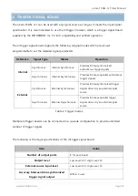
3. TRIGGER SIGNAL
Trigger Signal Connector Specifications
The oCam-1CGN-U-T accepts a external trigger signal through the 3-pin connector on the back
side of the camera. The pin descriptions are as follows:
Pin 1: Signal ground
Pin 2: For trigger signals in the range of 3V ~ 5V DC
Pint 3: For trigger signals in the range of 5V ~ 24V DC
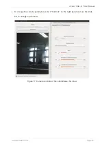
Figure 6. Pin description of the external trigger input signal connector
The circuit diagram of external trigger input is shown in the next figure. The input pins and the
internal circuit are isolated with a photo coupler. Therefore, the external input trigger signal
needs to supply more than 2 mA current to activate properly the trigger.
GND
Input pin for Trigger Signal (3V ~ 5V)
Input pin for
Trigger Signal (5V ~ 24V)