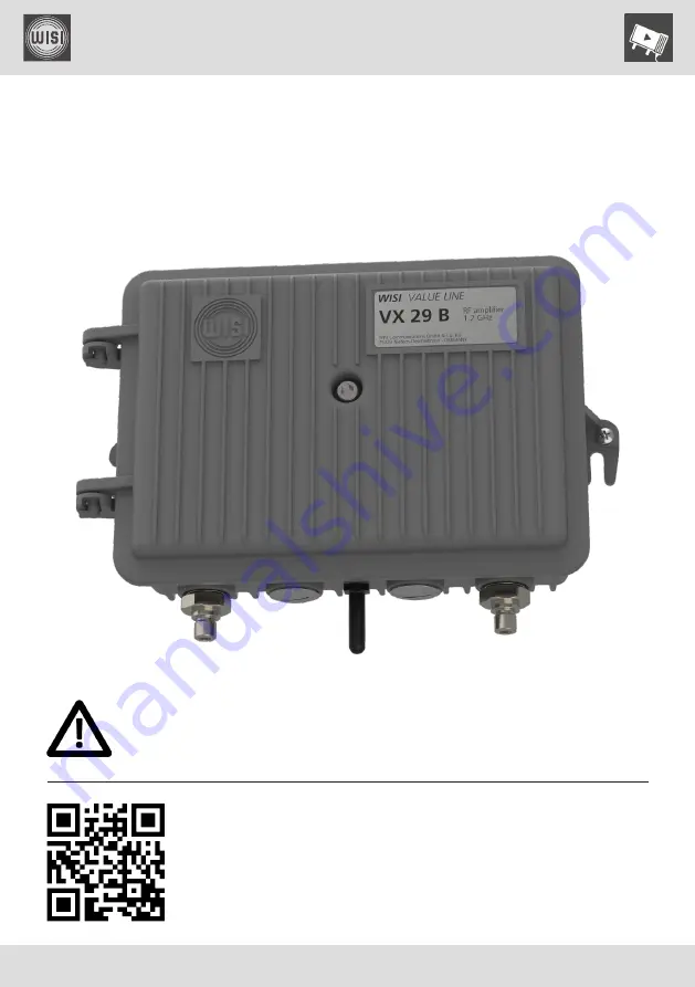
background image

Operating instructions

© WISI Communications GmbH & Co. KG

wisi.de

Stay up to date

For more information on your device, please visit our support 
website at 

wisiconnect.tv 

and browse to:

Please read the user instructions before using the equipment.

WISI

 VALUE LINE

VX 29 B series

RF amplifier, remotely powered

41

70

50

-a

 (0

7/

20

20

)

Knowledge Base > VX series > Products > VX 26 B / VX 29 B

bit.ly/wisivx2xb

Summary of Contents for 14MM-VX29B

Page 1: ...mation on your device please visit our support website at wisiconnect tv and browse to Please read the user instructions before using the equipment WISI VALUE LINE VX 29 B series RF amplifier remotely...

Page 2: ...n information Date Doc rev Document changes 07 07 2020 a First release FW v1 0 0 12 HFC manager v2 7 12 HFC updater v0 4 8 CE declaration of conformity Please find the declaration of conformity at our...

Page 3: ...8 3 2 Bluetooth interface basics 9 3 3 Device control using WISI HFC manager 11 3 4 Firmware updates and recovery using WISI HFC updater 12 3 5 Remote control via FSK receiver module VT 21 16 4 Confi...

Page 4: ...atic precautions when handling the equipment 1 2 Electrical safety Risk of bodily injury from electric shock Failure to adhere to these instructions could result in personal injury and or damage to el...

Page 5: ...type Description ZG 27 PG 11 case connection for WISI MK 15 cable ZG 28 PG 11 adapter F female ZG 35 A PG 11 adapter 3 5 12 female Input output configuration modules see section 4 1 WISI type Descript...

Page 6: ...ugh Output 1 Outer interfaces of the amplifier 2 3 Powering options NOTE The power supply partition of the equipment as well as all coaxial interfaces carrying remote power feeding contain dangerous v...

Page 7: ...cording fuse Each of the the fuse sockets also allows for the forwarding of the applied device supply voltage to the corresponding RF port Spare fuses use as F1 F4 Fuse socket F1 for input Fuse socket...

Page 8: ...not compatible Socket for handset control Position of the handset connector Handset basics Parameter menu keys Select parameter key Open parameter sub menu key Back Parameter sub menu keys Select dig...

Page 9: ...enna enables the radio connection to a smart phone or tablet The Android app WISI HFC Manager provides the GUI for the configuration of the fiber node whereas the WISI HFC updater brings firmware upda...

Page 10: ...Please activate the bluetooth bonding and change the key during the first setup in order to avoid unauthorized access Level 3 Access control list ACL Once paired a BT device is put on the access list...

Page 11: ...r When starting up the application the device scan listing will populate with the active bluetooth devices nearby Device scan list example Select your device and wait for the connection to be establis...

Page 12: ...ISI HFC updater You can use the WISI HFC updater app to update the amplifier s firmware via a bluetooth connection 3 4 1 Basic update procedure 1 When starting up the application the device scan listi...

Page 13: ...y be available if the particular device does support FW updates via bluetooth Update screen example 5 Double check the firmware versions Maybe you want to follow the link to our support website wisico...

Page 14: ...outcome of the update process Confirmation message example 8 Depending on your device settings you may have to re activate the bluetooth interface using the bluetooth button Then reconnect to the ampl...

Page 15: ...to identify the device type correctly the expert mode can help recover the unit either by choosing one of the included firmware images from the select file list or by importing an update file from yo...

Page 16: ...control via FSK receiver module VT 21 Compatible modules WISI type Description VT 21 FSK receiver module 868 MHz VT 21 B FSK receiver module 862 MHz VT 21 T FSK receiver module tunable The FSK receiv...

Page 17: ...E WISI Communications GmbH Co KG wisi de 17 VX 29 B series RF amplifier remotely powered Operating instructions 4 Configuration of signal transmission 4 1 General signal path setup Signal transmission...

Page 18: ...nput and output configuration WISI type Description Bridge XM 06 B Attenuator 0 dB 6 dB XM 51 B Splitter 4 dB 4 dB XM 53 B Tap 8 dB 2 dB XM 55 B Tap 13 dB 1 dB XM 56 B Tap 18 dB 1 dB XM 69 B Attenuato...

Page 19: ...the RF output ports 1 and 2 NOTE The insertion loss of the splitters and taps will affect the maximum available downstream level at the RF ports 4 1 2 Downstream option modules WISI type Description...

Page 20: ...0 25 dB 0 1 dB steps Handset Downstream InputEqualizer HFC manager DOWNSTREAM Input Eq Cable Sim 0 5 10 dB default 0 dB Handset Downstream CableSimulator Downstream interstage attenuator HFC manager...

Page 21: ...amplifier s input and output signals This enables spectral monitoring of downstream signals as following and moreover the auto alignment routine section 4 5 and the automatic level and slope control A...

Page 22: ...hannel table In order to obtain a meaningful representation of the spectrum analysis the RF channel table stored in the LR 45 should match your downstream channel lineup The channel table consists of...

Page 23: ...alignment 1 Make sure that the ALSC mode is set to off 2 Auto Alignment functionality is reliant on the number of reference channels pilots set to two pilots 3 Choose two channels from your RF channe...

Page 24: ...ns there will be a notification ALSC mode HFC manager ALSC ALSC Mode ALSC on ALSC off Handset ALSC Unit ALSC Mode Number of reference channels HFC manager AUTO ALIGNMENT Pilots one pilot two pilots Ha...

Page 25: ...ssful auto alignment HFC manager AUTO ALIGN ALSC after Alignment on off Handset ALSC Unit AALIG Start Xxx ON OFF Start the auto alignment HFC manager AUTO ALIGNMENT START Handset ALSC Unit AALIG Start...

Page 26: ...er of reference channels pilots from your RF channel lineup and set the pilot frequencies and the pilot modulation formats accordingly 4 Check the measured pilot levels at the reference frequencies Pl...

Page 27: ...requires regulation headroom in the settings of input attenuator and slope Thus normalization will fail with a corresponding error message if attenuator and or slope settings are too close to the bou...

Page 28: ...C on ALSC off Handset ALSC Unit ALSC Mode Pilot level deviation HFC manager ALSC Level 1 2 Dev read only Attenuator deviation HFC manager ALSC Input Att Dev read only Equalizer deviation HFC manager A...

Page 29: ...nce Normal steady state operation fail ALSC trying to reach lock in range ALSC newly activated Insufficient level detected frozen Attenuators and equalizers fixed on last valid value 30 seconds after...

Page 30: ...WISI VALUE LINE Operating instructions WISI Communications GmbH Co KG wisi de 30 VX 29 B series RF amplifier remotely powered space for your notes...

Page 31: ...WISI VALUE LINE WISI Communications GmbH Co KG wisi de 31 VX 29 B series RF amplifier remotely powered Operating instructions 5 Functional diagram...

Page 32: ...re Updates Datasheets Quick Guides Manuals Firmware Updates Known Issues List etc Entitlements for your Units after registration Forum You can discuss or share information about product configuration...

Reviews: