installation & connection
10_
installation & connection
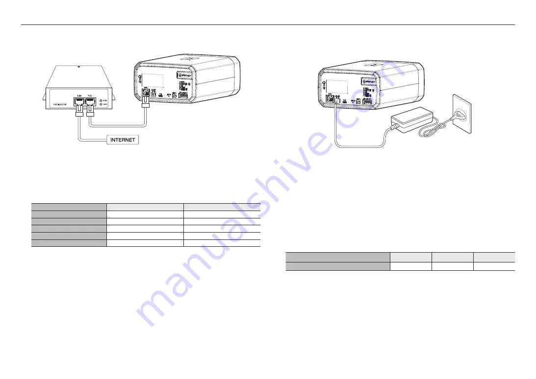
Powering and networking
Connect the PoE+ device with the PoE+ port of the camera.
J
`
Connect and use a PoE+ enabled router.
`
Use a
PoE+
device that complies with the IEEE 802.3at standard.
`
If you connect using a PoE+ enabled router, you don’t need a separate power supply cable to power it on.
Network Cable Specification
Item
Contents
Remark
Connector
RJ45 (10/100BASE-T)
Ethernet
10/100BASE-T
10/100 Mbps
Cable
Category 5e or higher
Max Distance
100 m
DC Resistance ≤ 0.125 Ω/m
PoE+ Support
IEEE 802.3at
Power Supply
Use the screwdriver to connect each line (+, –) of the power cable to the corresponding power port of the
camera.
J
`
If the power sources for PoE+ and DC 12 V are simultaneously turned on, the device power will be supplied by both of PoE+
and DC 12 V.
-
You can also use a router featuring PoE+ to supply power to the camera.
-
It is advisable to use only one power source from PoE+ and DC 12 V.
`
Be careful not to reverse the polarity when you connect the power cable.
`
When the power is initially turned on, time is needed to allow the screen stabilized. For this reason, a screen calibration is
performed when the power is initially turned on.
`
If you want to connect an external device, you must turn off the external device before proceeding.
`
Connect the set and the adapter power line first, and then connect the power cable to the outlet on the wall.
Power Cable Specification
In case of DC 12V Input:
Wire Type (AWG)
#20
#18
#16
Cable Length (Max.)
10m
17m
27m
Summary of Contents for TNM-3620TDY
Page 1: ...THERMAL NETWORK CAMERA User Manual TNM 3620TDY ...
Page 22: ......


