


22
ACW-DINDxxx_UG_EN_V1.8
6.
Uplinks on IoT networks (Sigfox/LoRaWAN)
a.
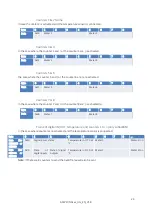
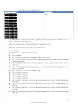
Test frame
This frame is sent to the network every minute for five minutes when the product is started. It can also
be triggered via the push button on the front of the ACW-DINDxxx. Each time this frame is sent, a
counter is incremented and inserted in the frame.
Frame format
Byte
0
1
Data
0x05
Cnt
Cnt
deals with the meter value.
b.
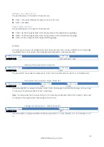
Keep alive frame
This frame is sent to the network periodically (configurable) and after transmission of the first 5 test
frames.
Frame format
Byte
0
1
2
3
4
5
Data
0x01
Power supply tension (millivolt)
Power supply tension (millivolt)
0x64
c.
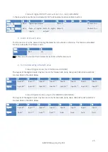
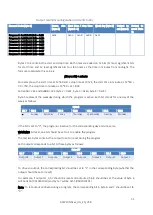
State frame
The state of the inputs and counters, as well as the temperature (if connected) are sent either
periodically or on change of state of a previously configured input.
To raise the status of all inputs and counters, it is possible that several frames are sent.
The frames below will be sent depending on the configuration.
Note : Disabled pins ("Disable" in the configurator) are replaced by 1 in bytes going back (byte 2 and
byte 3) the state of the inputs.
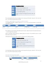
Note : The inputs logical state sent in the data bytes (byte 2 and byte 3) is inverted from the real logical
state. For example, for an input configured as a pull-up and a dry contact connected between the input
and the GND, the bit of this input will be 1 when the dry contact is closed, and it will be 0 when the dry
contact is open. For a pull-down and a dry contact connected between the input and the power supply,
it is the opposite, the input will be at 1 when the dry contact is open, and it will be at 0 when the dry
contact is closed.