background image

SmartPAC PRO User Manual 


1143100 

Chapter 3 – SmartPAC PRO Initialization Mode 


111 

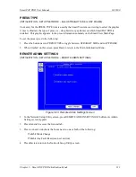
PRESS TYPE 

(INITIALIZATION 

– SETUP NETWORK – Select STRAIGHT SIDE or GAP FRAME) 

Your entry for the PRESS TYPE item is used by the SmartView remote viewing to select the graphic 
it uses to illustrate the type of  press (i.e., straight side or gap frame) on which SmartPAC PRO is 
installed.  This graphic appears  in the press information summary on the SmartView Main Page. 

To set the press type, do the following: 

1.


Press the button next to PRESS TYPE to toggle between STRAIGHT SIDE and GAP FRAME. 

2.


When finished on this screen, press Back to return to the Main Initialization Menu.  

REMOTE ADMIN SETTINGS 

(INITIALIZATION 

– SETUP NETWORK – REMOTE ADMIN SETTINGS) 


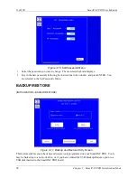
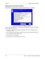
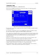
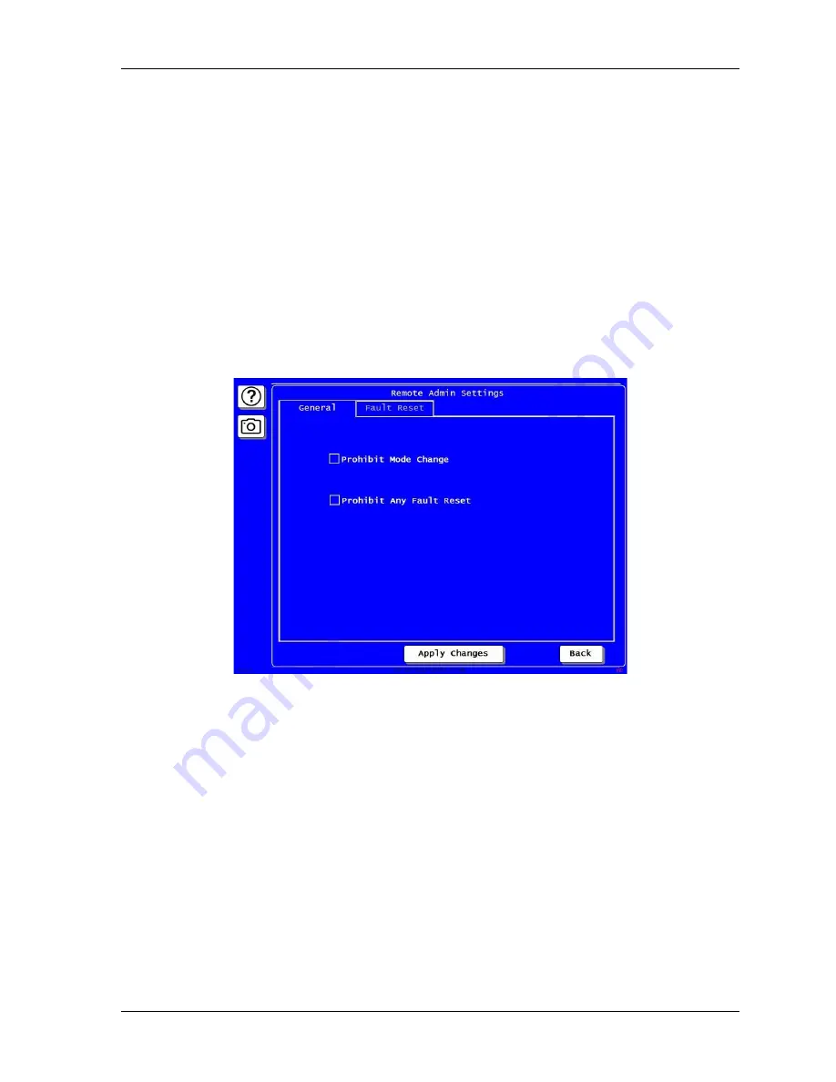
Figure 3-23. Remote Admin Settings Screen 

1.


In the Network Setup Utility screen, press REMOTE ADMIN SETTINGS. The Remote Admin 
Settings screen appears.  

2.


Press General to access the General tab. 

3.


Press to check or uncheck the boxes next to one or both of the following: 

Prohibit Mode Change  

Prohibit Any Fault Reset (see next section) 

4.


Press Back to return to the Network Setup Utility screen. 

Summary of Contents for SmartPAC PRO

Page 1: ......

Page 2: ......

Page 3: ...gure showing serial number on SD card Chapter 2 Added detail on wiring for pendant installation Chapter 2 Added or enhanced DiProPAC die protection features Chapter 6 Added S Codes to Chapter 8 SmartPAC PRO Fault Messages Added Appendices Appendix A SmartPAC Preventive Maintenance PM Monitor Optional Appendix B Updating SmartPAC PRO Firmware Appendix C Reporting Downtime and Scrap to SFC ...

Page 4: ......

Page 5: ...ng We ask that you email a PO to orders wintriss com for that amount or enclose the PO with the returned item This will enable us to ship the item back to you as soon as the repair has been completed If the item cannot be repaired or there are additional charges you will be contacted for approval Please be sure to carefully pack all returned items and ship to our Acton MA location Expedited Repair...

Page 6: ......

Page 7: ...SmartPAC PRO Specifications 41 Chapter 2 Installing SmartPAC PRO 43 Before You Start 45 Installation Guidelines 45 Terminating Cable Shields 46 Checking the Press 47 Mounting the SmartPAC PRO Control Enclosure 47 Installing SmartPAC PRO as a Panel Mount 48 Installing SmartPAC PRO in a Pendant 50 Installing the Resolver 52 Mounting the Resolver 54 Wiring the Resolver 54 Connecting Power Wiring AC P...

Page 8: ...y stop Circuit 83 Check Cam Channels ProCamPAC Only 83 Test Complete 83 What Next 83 Wiring Tables for Other SmartPAC PRO Connections 84 Chapter 3 SmartPAC PROInitializationMode 85 RESOLVER ZERO 86 POSITION SENSOR 86 POSITION SENSOR MODE 87 RESOLVER MOTION MODE Normal Motion Link Motion 87 ANGLE WHEEL ROTATION Clockwise Counterclockwise 87 COUNTER SETUP MODE 87 Counter Increment Mode 88 INSTALLED ...

Page 9: ...7 UPDATEFIRMWARE 117 System Init 118 Reset Initialization Data 118 Application Data Menu 120 Delete All Dashboards Favorites or Screen Captures 121 Disable Loss Rotation 122 Using SmartPAC PRO with a Link motion Press 122 Setting Link Motion 122 Using a ServoFeed Interface with Link Motion 123 Settling Time Compensation for Link Motion 123 Press Speed Compensation for Link Motion 124 Chapter 4 Sma...

Page 10: ... Safety Distance 150 PRESS SPEED 151 TOOL INFORMATION 153 ERROR EVENT LOG 153 LOAD NEW TOOL 154 MESSAGING 156 Chapter 6 Using DiProPAC Die Protection Optional 159 DiProPAC in Initialization Mode 161 Sensor Names 161 Entering Global Sensor Names 162 SENSOR ENABLE MODE 164 Selecting Sensor Enable Mode 165 Enabling Setup Mode 165 DiProPAC Die Protection in Program Mode 166 Selecting Sensor Enable Mod...

Page 11: ...ial Sensors 198 Viewing the Sensor Summary 198 Viewing Sensor Status 199 Chapter 7 Using ProCamPAC Programmable Cams 201 ProCamPAC Programmable Cam Switch 202 Initialization 202 SELECT CAM NAMES ProCamPAC 202 AUTO ADVANCE and Slow RPM ProCamPAC 204 Calculating the Auto Advance Constant 205 Setting Auto Advance Constants and Slow RPM 205 SET GLOBAL CAMS Optional 206 ProCamPAC in Program Mode 208 Pr...

Page 12: ... error ES 229 S30 Program memory checksum 1 fault 230 S31 Program memory checksum 2 fault 230 Messages for Sensor Faults 230 Green sensor missed 230 Green sensor actuated late 230 Green sensor failure 231 Green constant fault 231 Green quick check sensor actuated outside ready 231 Green special fault 231 Fault message for yellow sensors This N O sensor is grounded 232 Fault message for red sensors...

Page 13: ...AC PRO Firmware 251 Installing Updated Firmware from USB Disk to SmartPAC PRO 252 Appendix C Reporting Downtime and Scrap to SFC 255 Machine States to Which SFC Logs Press Time 255 SmartPAC PRO Downtime Reporting Features 256 Forced Idle Dialog Mode 256 Backfilling vs Forward Filling 256 Putting the Press Back on Line 257 Forced Error Dialog Mode 259 Persist Dialog Mode 260 Single stroke Mode 260 ...

Page 14: ...tended Wiring Configuration Figure 9 120 240VAC SmartPAC PRO with Remote RTS Wiring Configuration Figures Figure 1 1 SmartPAC PRO Front Panel 26 Figure 1 2 Top Screen for each of SmartPAC PRO s 3 Operating Modes 30 Figure 1 3 Numeric Keypad 32 Figure 1 4 SmartPAC PRO On screen Keyboard 33 Figure 1 5 Save to USB Disk 35 Figure 1 6 USB Transfer Complete 36 Figure 1 7 USB Disk Error Message 36 Figure...

Page 15: ...n Initialization Menu 85 Figure 3 2 Position Sensor Screen 86 Figure 3 3 Installed Options Screen 89 Figure 3 4 Select Language Screen 89 Figure 3 5 Options Manager Screen 90 Figure 3 6 Press Name Entry Window 91 Figure 3 7 Press Control Parameter Menu 92 Figure 3 8 Security Access Menu 94 Figure 3 9 Enter Your Password Screen 95 Figure 3 10 Set Passwords Menu 98 Figure 3 11 Backup and Restore Uti...

Page 16: ...Light Curtains and Press Showing Safety Distance 151 Figure 5 7 Press Speed Parameters Screen 151 Figure 5 8 Tool Information Screen 153 Figure 5 9 Error Event Log 154 Figure 5 10 Tool Manager Screen 155 Figure 5 11 Load Tool Warning Window 155 Figure 5 12 Messaging Screen 156 Figure 5 13 Select Recipients 156 Figure 5 14 Select Message Window 157 Figure 5 15 Select Attachments Window 158 Figure 5...

Page 17: ...igure 6 34 Sensor Program Screen 190 Figure 6 35 Sensor Summary Screen 191 Figure 6 36 Sensor On Off Status 192 Figure 6 37 Sensor Turned Off Message 193 Figure 6 38 Main Run Menu with SENSORS DISABLED 194 Figure 6 39 Disable Sensors Confirmation Message 195 Figure 6 40 Sample Die Protection Run Mode Menu 196 Figure 6 41 Ready Signal Programming Screen 196 Figure 6 42 Sensor Summary Screen 198 Fig...

Page 18: ...ng Sensors 9 16 64 Table 2 6 DiPro Sensor Interface DSI 2 to SmartPAC PRO Wiring Sensors 17 24 65 Table 2 7 DiPro Sensor Interface DSI 2 to SmartPAC PRO Wiring Sensors 25 32 66 Table 2 8 ProCamPAC to Cam Output Assembly SMARTPAC PRO01 Wiring Cams 1 8 70 Table 2 9 ProCamPAC to Cam Output Assembly SMARTPAC PRO01 Wiring Cams 9 16 70 Table 2 10 Connections to Relays 71 Table 2 11 Aux I O TB5 Wiring 73...

Page 19: ...ts to programmed settings Chapter 6 shows you how to use the DiProPAC die protection option in all three operation modes Chapter 7 shows you how to use the ProCamPAC programmable cam option in all three operation modes Chapter 8 provides explanations of the messages that display on the SmartPAC PRO front panel when a fault condition occurs or a counter preset is reached and shows you how to correc...

Page 20: ......

Page 21: ...voided will result in death or serious injury A WARNING symbol indicates a potentially hazardous situation which if not avoided could result in death or serious injury CAUTION A CAUTION indicates a potentially hazardous situation which if not avoided may result in property damage NOTICE A NOTICE symbol indicates important information that you should remember including tips to aid you in performanc...

Page 22: ......

Page 23: ...improper installation misuse misapplication negligence accident or unauthorized modification The provisions of this warranty do not extend the original warranty of any product which has either been repaired or replaced by Wintriss Controls No other warranty is expressed or implied Wintriss accepts no liability for damages including any anticipated or lost profits incidental damages consequential d...

Page 24: ......

Page 25: ...h Optional 29 SmartPAC PRO s Modes of Operation 29 Initialization Mode 31 Program Mode 31 Run Mode 31 SmartPAC PRO User Interface 32 On Screen Numeric Keypad 32 On Screen Keyboard 33 Control and Navigation Buttons 34 Screen Captures 35 Saving Directly to a USB Drive 35 Exporting Saved Screen Capture Images to a USB Disk 36 View Screen Capture Images on SmartPAC PRO 36 Creating and Using Dashboards...

Page 26: ...enabling press operation to be monitored remotely and messages to be sent to and from the SmartPAC PRO control SmartPAC PRO can be configured with the following options Up to 32 sensor die protection system Up to 16 channel programmable cam switch Up to 32 sensor in die measurement system Solid state dual microprocessor based clutch brake control Two or four input load and signature monitoring Aut...

Page 27: ...tics and error log information from the SmartPAC PRO SmartPAC PRO upgrades and enhancements can be installed quickly and easily Upgrades can be either downloaded directly to SmartPAC PRO via the local network or installed via a USB disk SmartPAC PRO Options For additional information on any of these SmartPAC PRO options and capabilities contact your Wintriss Sales Representative or Wintriss Custom...

Page 28: ...RO front panel flashes when press stopping time approaches within 10msec of the stop time limit allowing you to schedule maintenance Set counters SmartPAC PRO s counters keep track of the number of strokes made by the press the number of good parts produced the total hits on the die The good parts counter increments only when the die protection or tonnage monitoring option does not generate a faul...

Page 29: ...The optional ProCamPAC module enables you to connect up to eight or sixteen cam channels to your equipment ProCamPAC consists of a PC board that you install in your SmartPAC PRO and a separate assembly that contains the relays that open and close on signals from SmartPAC PRO Different types of relays can be used depending upon the voltages of your equipment and your special needs Refer to Chapter ...

Page 30: ...n dark blue display Make settings that control operation of SmartPAC PRO with all tools You use Initialization mode extensively when you install a new SmartPAC PRO You will use this mode only occasionally after you set up SmartPAC PRO and the press is running See next section and Chapter 3 Turn the key switch to PROG and select INITIALIZATION MENU from the Main Programming Menu We recommend that y...

Page 31: ...ch make sure SmartPAC PRO is in the Main or top menu for the mode it is in If it is not press Reset Exit or Back repeatedly until the Main menu appears Initialization Mode Initialization mode allows you make settings that control the operation of SmartPAC PRO with any tool See Chapter 3 page 85 for detailed instructions on how to use SmartPAC PRO in Initialization mode Settings for individual tool...

Page 32: ...the USB port on the front panel of the SmartPAC PRO When entering alphanumeric data the SmartPAC PRO will automatically recognize keystrokes from the on screen keyboard keypad and the external USB keyboard On Screen Numeric Keypad Whenever you select a field that requires numbers only SmartPAC PRO displays an on screen numeric keypad see Figure 1 3 Figure 1 3 Numeric Keypad The up and down arrows ...

Page 33: ... without making any changes and Enter accepts the value entered into the field Shift capitalizes the next character CAPS functions like a Caps Lock key When a USB keyboard is used the ESC key acts as the Cancel button while the other keys match their counterparts Figure 1 4 SmartPAC PRO On screen Keyboard NOTICE When the on screen keypad or keyboard is displayed Exit or Back button on the screen i...

Page 34: ...es for programmable limit switch outputs and die protection ready signals Use the ENTER button to select a highlighted item or to register a value entered It can also toggle values Dashboard button on Run screen Press to go to the currently selected dashboard See Favorite button and Creating and Using Dashboards page 36 Favorite button on Run screens Press this button to create a dashboard or sele...

Page 35: ... to a USB Drive If there is a USB drive in SmartPAC PRO s USB port the SmartPAC Pro creates a folder on the drive labelled CaptureXXXXXXXX where XXXXXXXX is the SmartPAC PRO s serial number The screen captures are stored in this folder until the USB Disk is full You can retrieve the internally stored screen captures and other diagnostic information from the SmartPAC PRO by plugging a USB drive int...

Page 36: ...sfer Complete If you attempt to download to USB disk without first plugging one into the USB Port SmartPAC Pro displays an error see Figure 1 7 Figure 1 7 USB Disk Error Message View Screen Capture Images on SmartPAC PRO Press and hold down the Camera button for 5 seconds The Image Viewer window appears showing one of the stored screen captures with the data and time it was captured It is marked I...

Page 37: ... Screen Figure 1 10 Add Screen to Favorites To remove favorites or dashboard screens 1 In the Favorites screen press Edit A red X appears on each favorite or dashboard screen Figure 1 11 2 Press the red X to remove each item 3 When done press Save To exit without deleting any screens press Cancel ...

Page 38: ... follow these steps 1 In Run Mode press the Favorites star button to open the Favorites screen 2 On the Favorites Screen press Create Dashboard The Dashboard Configuration screen appears Figure 1 12 Dashboard Configuration Screen 3 Press the button next to 1x2 or 2x2 to select whether to show two or four items on the dashboard See Figure 1 13 and Figure 1 14 ...

Page 39: ...een enter a name for the dashboard and populate each display area Press on the desired item at left and drag it to the appropriate area Figure 1 15 Dashboard Configuration Screen Display Area 1 Filled 5 As you populate the dashboard press Preview to see a preview of the screen 6 Press Done to return to the Dashboard Configuration screen Continue configuring this dashboard as needed ...

Page 40: ... 16 Dashboard Configuration Preview 7 When you are satisfied with the dashboard press Save Showing the Currently Selected Dashboard In any Run screen press the Dashboard button Figure 1 17 to display the last dashboard you selected on the Favorites screen Figure 1 17 Dashboard Button ...

Page 41: ...2 ft 2000 m Display 12 1 in 307 mm color active matrix TFT liquid crystal display LCD Power LED Brake Warning LED Memory Allows storage of settings for 2000 tools Speed 7 1600 SPM Accuracy 2 3 1 33 for high speed version Counters Good parts strokes 3 batch with presets 7 digits Number of hits on tool counter counts all hits on tool resettable to 0 after maintenance Inputs Outputs Inputs for resolv...

Page 42: ...1143100 SmartPAC PRO User Manual 42 Chapter 1 Introduction to SmartPAC PRO ...

Page 43: ...be used to provide timing signals for any safety use including clutch brake control or muting of light curtains Failure to comply with these instructions will result in death or serious injury NOTICE OPTIONAL MODULES PROCAMPAC AND DIPROPAC INCLUDED IN MANUAL When you order your SmartPAC PRO you may include the DiProPAC die protection and or ProCamPAC programmable cam switch option This manual incl...

Page 44: ...m Channels 66 Wiring Setup Mode Circuit 73 Wiring a Remote Reset Switch Optional 73 Wiring a Sensor Disabled Output Optional 73 Wiring the ProCamPAC Output with Your Mechanical Top Stop Cam Switch Optional 74 Zeroing the Resolver 75 Turning on Power to SmartPAC PRO 75 Verifying Installation of DiProPAC and or ProCamPAC Optional 76 Moving the Ram to Top Dead Center TDC 77 Setting the Resolver Zero ...

Page 45: ...re Run one or two low voltage conduits for the resolver and communications control wires into the lower left hand corner of SmartPAC PRO If you have top stop and emergency stop circuits that are 24V or a voltage other than 120V you must run them separately from the high voltage wiring Never use the SmartPAC PRO power terminals as a junction point to provide power for external devices In most cases...

Page 46: ...SmartPAC PRO display separately in a pendant for example see wiring diagrams Figure 7 and Figure 8 for connection details Terminating Cable Shields NOTICE TERMINATE CABLE SHIELDS CORRECTLY TO MINIMIZE ELECTROMAGNETIC INTERFERENCE EMI Shielded cables are used with the SmartPAC PRO For effective shielding terminate the cable shields as near as possible to the terminal block you are wiring to NOTICE ...

Page 47: ... where you connect SmartPAC PRO Set the press ram to top dead center TDC NOTICE MOVE RAM TO TDC BEFORE INSTALLING SMARTPAC PRO This is an important step because the press must be at top dead center TDC when you make final adjustments for the resolver Be accurate when setting the press to TDC Set to 0 2 Use a dial indicator on the face of the ram if necessary Mounting the SmartPAC PRO Control Enclo...

Page 48: ...clearance behind the panel mounting plane to leave enough room for the electronics 1 Determine a convenient location within your enclosure or console for mounting SmartPAC PRO Ideally SmartPAC PRO should be mounted where operators and setup personnel can easily see the readouts and reach the display 2 Cut out a hole in your enclosure and drill and tap twelve holes for 10 32 screws referring to Fig...

Page 49: ...SmartPAC PRO User Manual 1143100 Chapter 2 Installing SmartPAC PRO 49 Figure 2 2 SmartPAC PRO Panel Mount Cutout Dimension ...

Page 50: ... the SmartPAC PRO display in a pendant install the HMI board display in the pendant and install the RTS board in the cabinet If the wiring run between the boards is less than 16 ft 4 9 m you can use a shielded USB cable to make the connection If the wiring run is longer than 16 ft use an extender kit See Table 2 1 Figure 2 4 and wiring diagram Figure 9 for details ...

Page 51: ...nce between HMI display board and RTS board Connect with 10 ft 3 0 m USB cable 10 ft 3 0 m P N 2313203 16 ft 4 9 m USB cable 16 ft 4 9 m P N 2313204 16 ft 4 9 m Extender kit P N 4351601 and the appropriate length Ethernet cable ordered separately 30 ft 7 6 m P N 2315902 50 ft 15 2 m P N 2315903 100 ft 30 5 m P N 2315904 Figure 2 4 Pendant Installation ...

Page 52: ...ns the resolver sprocket Use a pin or other method to fix the location of the sprocket on the crankshaft Failure to comply with these instructions will result in death or serious injury The resolver see Figure 2 5 for dimensions provides SmartPAC PRO with the exact position of the crankshaft at every angle throughout the stroke see Resolver based Operation page 28 To deliver this precision the res...

Page 53: ...tion of rotation by swapping the black and yellow wires on the resolver connector see Table 2 2 page 55 When designing the drive for the resolver make sure that the drive allows for adjustment of the resolver to its zero position at top dead center All sprockets must be keyed or pinned The resolver shaft has a standard key Design a method of driving the resolver directly from the crankshaft using ...

Page 54: ...ing the resolver s keyway aligned with the arrow within 5 attach the chain or drive mechanism Wiring the Resolver Wire the resolver as follows referring to Table 2 2 page 55 1 Find the resolver cable if it is not connected to the resolver Plug the end with the connector into the resolver It only goes one way Twist the locknut so the connection is tight 2 Run the resolver cable through 1 2 in condu...

Page 55: ...ptacle on the SmartPAC PRO board It can plug in only one way Table 2 2 Resolver Wiring Resolver Cable Wire Color Pin on TB3 CW Rotation CCW Rotation 212 GND No connection 213 S1 Black Yellow 214 S2 Green 215 R1 Red 216 S3 Yellow Black 217 R2 Orange 218 S4 Brown Terminate the cable shield to the ground stud nearest the cable entry Connecting Power Wiring AC Powered Units ELECTRIC SHOCK HAZARD Do no...

Page 56: ...ly to the press control transformer at the press control For 115 Vac you need three wires high black neutral white and ground green For 230 Vac wires are black and red with green or green yellow for ground 3 Connect the AC input wires and ground wire as shown in Figure 2 7 and Figure 4 at the back of the manual Make your ground connection as follows SmartPAC PRO Enclosure Connect your ground green...

Page 57: ...ous injury Connecting Stop Circuits and Input Check Circuit You need four wires to connect SmartPAC PRO to your press control stop circuits two for the emergency stop circuit and two for the top stop circuit You can wire these circuits at your press control Refer to your press control manual or other electrical prints You need two wires to connect to the input check circuit These wires are connect...

Page 58: ... TB4 Circuit SmartPAC PRO TB 4 Pin Locations Input check A 205 Input check B 206 E stop 207 E stop 208 Top stop 209 Top stop 210 3 Plug the connector back into its socket Double check connections to make sure that you did not wire the connector backward 4 Connect top stop E stop and input check circuit wires at the press control or other box into which you are tying them NOTICE Be sure to number a...

Page 59: ...ety valve relay to start the press voltage is induced across the input check circuit If SmartPAC PRO gets no signal from the resolver within the specified start time limit resolver not turning SmartPAC PRO opens the emergency stop circuit and a loss of rotation fault message is displayed on the screen The fault indicates that the resolver belt or chain is broken or so loose that the resolver shaft...

Page 60: ...t recognize that the option is installed Eight 16 and 32 channel configurations of the same option are interchangeable When a board is installed in the correct location SmartPAC PRO recognizes whether it is an 8 16 or 32 channel version of DiProPAC or an 8 or 16 channel version of ProCamPAC NOTICE For information about using the DiProPAC or ProCamPAC options see Chapter 6 Using DiProPAC Die Protec...

Page 61: ...irection 3 When the board is properly seated screw it down to the four standoffs using the screws that came with the kit 4 Remove the connector s from the board one connector for an 8 sensor or 8 cam unit two connectors for a 16 sensor or 16 cam unit four connectors for a 32 sensor unit Terminal block assignments for these different boards are as follows See Figure 2 12 DiProPAC 8 Sensors 1 8 to T...

Page 62: ...To connect your DiPro die protection sensors through the DiPro Sensor Interface DSI 2 refer to Table 2 4 to wire sensors 1 8 Table 2 5 to wire sensors 9 16 Table 2 6 to wire sensors 17 24 Table 2 7 to wire sensors 25 32 Refer to wiring diagrams at the end of the manual Figure 1 for sensors 1 16 Figure 2 for sensors 17 32 Refer to the DSI 2 manual for more information Terminate cable shields as clo...

Page 63: ...SENSOR 1 282 SENSOR 1 Red 2 SENSOR 2 283 SENSOR 2 Orange 3 SENSOR 3 284 SENSOR 3 Yellow 4 SENSOR 4 285 SENSOR 4 Green 5 SENSOR 5 286 SENSOR 5 Blue 6 SENSOR 6 287 SENSOR 6 Violet 7 SENSOR 7 288 SENSOR 7 Gray 8 SENSOR 8 289 SENSOR 8 No connection 290 Sensor power Black 9 GND 291 GND 10 GND No connection 11 5 VDC No connection Shield Terminate drain wire to ground stud Terminate drain wire to ground ...

Page 64: ...SOR 1 292 SENSOR 9 Red 2 SENSOR 2 293 SENSOR 10 Orange 3 SENSOR 3 294 SENSOR 11 Yellow 4 SENSOR 4 295 SENSOR 12 Green 5 SENSOR 5 296 SENSOR 13 Blue 6 SENSOR 6 297 SENSOR 14 Violet 7 SENSOR 7 298 SENSOR 15 Gray 8 SENSOR 8 299 SENSOR 16 No connection 300 Sensor power Black 9 GND 301 GND 10 GND No connection 11 5 VDC No connection Shield Terminate drain wire to ground stud Terminate drain wire to gro...

Page 65: ...SOR 1 180 SENSOR 17 Red 2 SENSOR 2 181 SENSOR 18 Orange 3 SENSOR 3 182 SENSOR 19 Yellow 4 SENSOR 4 183 SENSOR 20 Green 5 SENSOR 5 184 SENSOR 21 Blue 6 SENSOR 6 185 SENSOR 22 Violet 7 SENSOR 7 186 SENSOR 23 Gray 8 SENSOR 8 187 SENSOR 24 No connection 188 Sensor power Black 9 GND 189 GND 10 GND No connection 11 5 VDC No connection Shield Terminate drain wire to ground stud Terminate drain wire to gr...

Page 66: ...FETY USE Use SmartPAC PRO s programmable cam switch to control auxiliary functions only The SmartPAC PRO programmable cam capability should never be used to provide timing signals for any safety use including clutch brake control or muting of light curtains Failure to comply with these instructions will result in death or serious injury CAUTION BOARD DAMAGE OR SHORT CIRCUIT WHEN MOUNTED WITHOUT EN...

Page 67: ...al solid state relays can be plugged only into slots labeled K306 K308 K310 and K312 which are channels 5 8 Locate the 12 conductor cable s for wiring the ProCamPAC board solid state relay into channel 5 location K306 you cannot plug a standard relay into location K305 See Figure 2 14 Example Say you wish to use three standard relays and one solid state relay You would install the three standard r...

Page 68: ... s from its socket on the ProCamPAC board TB401 for an 8 channel ProCamPAC TB451 and TB452 for a 16 channel ProCamPAC Connect wires from the 12 conductor cable s to the pin locations on the appropriate terminal blocks as shown in Table 2 8 for the 8 channel option or Table 2 8 and Table 2 9 for the 16 channel option See also wiring diagram Figure 3 at the end of the manual ...

Page 69: ...ard Connections to control DS301 Sockets for solid state relays only Channels 5 through 8 CH8 CH7 CH6 CH5 CH4 CH3 CH2 CH1 139 7 Sockets for standard relays Channels 1 through 8 NOTE For channels 5 8 plug in standard or solid state but not both CHAN 8 CHAN 7 CHAN 6 CHAN 5 CHAN 4 CHAN 3 CHAN 2 CHAN 1 Terminals for connecting wires to equipment Clearance hole for 6 screw 4 places ...

Page 70: ...2 cams 9 16 Pin 2nd Cam Output Board TB301 Pin CHAS 1 White Relay Pwr 281 A 3 Black GND 280 B 2 Red 5 279 5 Vdc 4 Tan Ch 16 278 Ch 8 5 Pink Ch 15 277 Ch 7 6 Gray Ch 14 276 Ch 6 7 Blue Ch 13 275 Ch 5 8 Yellow Ch 12 274 Ch 4 9 Orange Ch 11 273 Ch 3 10 Purple Ch 10 272 Ch 2 11 Brown Ch 9 271 Ch 1 12 7 Plug the connector s back into the socket s 8 Run the cable s through conduit to TB301 in the ProCam...

Page 71: ...ne wire to N O polarity does not matter SPST WARNING INCORRECT SUPPRESSOR INSTALLATION MAY CAUSE RELAYS TO REMAIN ENERGIZED Ensure that suppressors are correctly installed They must not be installed across the relay contacts inside the ProCamPAC Output enclosure If a suppressor is installed across the relay contacts and it fails shorted the equipment controlled by that relay will remain energized ...

Page 72: ...1143100 SmartPAC PRO User Manual 72 Chapter 2 Installing SmartPAC PRO Figure 2 15 Installing Suppressors Across an AC Load Figure 2 16 Installing a Diode Across a DC Load ...

Page 73: ...your electrical prints or the manual for your press control to plan your wiring Table 2 11 Aux I O TB5 Wiring Pin Signal 245 24 V 246 POSITION SENSOR 247 GND 248 ZERO 249 REMOTE RESET 250 GND 251 LOCKOUT 252 INCH SETUP 253 OP STA 2 254 OP STA 1 Wiring a Remote Reset Switch Optional Like the Setup mode terminal the Remote Reset terminal can be wired to a normally open switch to activate the circuit...

Page 74: ... Auto compensated Top Stop ACTS Test the system after wiring as described below to ensure proper functioning of the Top stop circuit Failure to comply with these instructions could result in death or serious injury The diagrams provided in Figure 2 17 show how to wire ProCamPAC and your mechanical cam switch for Top Stop This optional top stop wiring only aids in adjusting the top stop and in util...

Page 75: ...next Turning on Power to SmartPAC PRO To turn on power to SmartPAC PRO do the following 1 Make sure there is no die in the press 2 Turn the PROG RUN keyswitch to PROG 3 Power up the SmartPAC PRO The green Power light on the SmartPAC PRO front panel illuminates the display shows various startup screens and the Brake Warning LED flashes at approximately two second intervals while SmartPAC PRO comple...

Page 76: ...C PRO board and the display Power up SmartPAC PRO again If the display remains off contact Wintriss Tech Support Verifying Installation of DiProPAC and or ProCamPAC Optional If you installed DiProPAC and or ProCamPAC on SmartPAC PRO you need to verify that the installation was done correctly and that the option is available Do the following 1 On the SmartPAC PRO Main Program Menu select INITIALIZA...

Page 77: ...COUNTERS page 134 3 Load the tool following the instructions in Loading a Tool page 130 4 Turn the PROG RUN keyswitch to RUN and inch the press to 0 2 NOTICE USE A DIAL INDICATOR TO DETERMINE TDC Do not rely on the SmartPAC PRO display to indicate when the press has reached TDC Until the resolver is zeroed displayed values are inaccurate Use a dial indicator or some other means to determine 0 5 Wh...

Page 78: ...sor Optional CAUTION MISALIGNMENT OF RESOLVER AND CRANKSHAFT If you have installed the position sensor enable it during initialization and leave it enabled even though it is optional for SmartPAC PRO operation If you disable the position sensor to clear an error message misalignment between the resolver and crankshaft will go undetected Failure to comply with these instructions could result in pro...

Page 79: ...agnet should be mounted so the switch senses it for at least 10 to 15 of the stroke For best results at higher press speeds mount the magnet on a shaft of 2 in to 3 in about 50 75 mm diameter As shown in Figure 2 21 the larger the diameter of the shaft the shorter the dwell the period during which the switch senses the magnet To obtain a longer dwell therefore mount the magnet on a shaft of smalle...

Page 80: ...o NOTICE The crankshaft angle reading should increase as you inch the press If it decreases 359 358 357 for example swap the black and yellow wires terminals 213 and 216 on connector TB3 on the SmartPAC PRO board see Table 2 2 page 55 and Figure 2 6 page 53 NOTICE The press must be at top dead center 0 before the position sensor can be installed Make sure that the CURRENT RESOLVER ANGLE setting is...

Page 81: ...since you installed the sensor If it has move the ram to TDC i e 0 and re install the magnet see step 14 If the ram hasn t moved check the distance between the magnetic switch and the magnet Re adjust if necessary If a Position Sensor Incorrect error message displays after you try running the press see step 22 the position sensor may not have enough dwell to provide an adequate signal at high spee...

Page 82: ...e tool following the instructions in Loading a Tool page 130 then turn the PROG RUN keyswitch to RUN Check and Set Direction of Rotation of Resolver 4 Inch the press Watch the crankshaft angle reading inside the crank angle clock at the lower left of the display The crankshaft angle should increase as you inch the press If it decreases 359 358 357 for example swap the black wire and yellow wire te...

Page 83: ...iring and trace the cause of the problem Check Cam Channels ProCamPAC Only 8 Create some test settings for your cam channels in Program mode see Run Mode CAM SWITCH ProCamPAC page 218 load the tool settings and switch to Run mode to run the press Ensure that the equipment feed blow off lube etc controlled by each channel is operating appropriately according to the settings you made Test Complete 9...

Page 84: ...l Port Pin Signal Port 235 RXD1 SFI PORT 1 224 RXD3 SPECIAL PORT 3 236 RXD1 225 RXD3 237 TXD1 226 TXD3 238 TXD1 227 TXD3 239 TXD1 228 TXD3 240 GND 229 GND 241 RXD2 MODULE PORT 2 230 RXD4 PORT 4 242 RXD2 231 RXD4 243 TXD2 232 TXD4 244 TXD2 233 TXD4 234 TXD4 Table 2 14 Spare 1 Port 5 and WPC Port 6 TB8 Wiring Pin Signal Port 330 TXD6 WPC PORT 6 329 TXD6 328 RXD6 327 RXD6 326 GND 325 TXD5 324 TXD5 SP...

Page 85: ...menu The following sections cover zeroing the resolver enabling the position sensor setting the brake monitor controlling security access setting communications parameters and other operations It also documents functions related to programmable cams and die protection such as entering custom cam channel and sensor names and setting global cams If you have SmartPAC PRO options installed also make I...

Page 86: ...SENSOR INITIALIZATION POSITION SENSOR CAUTION MISALIGNMENT OF RESOLVER AND CRANKSHAFT If you have installed the position sensor enable it during initialization and leave it enabled even though it is optional for SmartPAC PRO operation If you disable the position sensor to clear an error message misalignment between the resolver and crankshaft will go undetected Failure to comply with these instruc...

Page 87: ...ing is NORMAL MOTION If your SmartPAC PRO is installed on a link motion press for instructions go to Using SmartPAC PRO with a Link motion Press page 122 ANGLE WHEEL ROTATION Clockwise Counterclockwise INITIALIZATION POSITION SENSOR This setting controls the rotational direction of the crank angle clock on the SmartPAC PRO display The default setting is CW Clockwise If you want the crank angle clo...

Page 88: ...is displayed press Back Counter Increment Mode This item allows you to specify whether the Good Parts counter increments during a fault condition The default setting NO INC FAULT prevents the counter from incrementing when there is a fault To set this parameter do the following 1 Press ENTER to toggle between two settings NO INC FAULT The Parts counter and batch counters whose increment mode is pr...

Page 89: ... channels and sensors Figure 3 3 Installed Options Screen Your screen will look different If you ordered the alternate language option this screen provides a SELECT LANGUAGE button to select the language in which you want SmartPAC PRO screens displayed if you have the appropriate option When you press the Select Language button a screen similar to Figure 3 4 displays Figure 3 4 Select Language Scr...

Page 90: ...ager screen opens Each option that is installed can be enabled or disabled Options not installed are marked Unlicensed 2 To enable or disable an option press the box next to the option name to toggle between Enabled and Disabled 3 When finished on this screen press Apply and Restart to accept the changes SmartPAC PRO restarts with the new settings To leave this screen without making any changes pr...

Page 91: ...artPAC PRO is integrated with WPC 2000 press control These settings are made on the Press Control Parameter screen Figure 3 7 The stopping time is the time that it takes the crankshaft to stop once the dual safety valve DSV has been de energized The Brake Monitor checks the stopping time of the press on each time it stops If the stopping time comes within 10 milliseconds of the stop time limit the...

Page 92: ...t as the stop time limit on the Brake Monitor screen must factor in the normal wear on your brake to prevent SmartPAC PRO from generating stop time faults when the stopping time increases only a little The stop time limit can be easily calculated based on the actual stopping time of your press To perform this calculation do the following 1 In Run Mode perform the procedure Determining the Stopping...

Page 93: ... arrows to highlight the value for STOP LIMIT Press ENTER A numeric entry window appears 4 Key in a value maximum is 1000 milliseconds and press Enter You are returned to the Press Control Parameter menu with the value you entered displayed 5 Use the up and down arrows to highlight the value for START LIMIT Press Enter A numeric entry window appears 6 Key in a value maximum is 1000 milliseconds an...

Page 94: ... on the Security Access Menu you can specify three types of access PROGRAM AND RUN MODES Allows users to change settings in both Program and Run modes This access type is the least secure PROGRAM MODE ONLY Allows users to change settings only in Program mode i e when the PROG RUN keyswitch is in the PROG position To prevent users from entering the Program mode you should remove the PROG RUN keyswi...

Page 95: ...ALC ONLY NO RECALC ADJUST and PASSWORD REQUIRED CHG TOOL TEMPLATE This item has two options PASSWORD REQUIRED and PASSWORD NOT REQUIRED When you attempt to access a menu that is password protected SmartPAC PRO displays a window Figure 3 9 that asks you to enter your password Figure 3 9 Enter Your Password Screen NOTICE IF YOU FORGET OR DO NOT KNOW YOUR PASSWORD S Call Wintriss Tech Support at the ...

Page 96: ...OL TEMPLATE PASSWORD REQUIRED PASSWORD NOT REQUIRED ADJ PROPAC SENS PROGRAM AND RUN MODES PROGRAM MODE ONLY PASSWORD REQUIRED ADJ DIPRO SENS PROGRAM AND RUN MODES PROGRAM MODE ONLY PASSWORD REQUIRED DISABLE SENSORS PROGRAM AND RUN MODES PROGRAM MODE ONLY PASSWORD REQUIRED TURN OFF SENSORS ALLOWED NOT ALLOWED PASSWORD REQUIRED ADJUST CAMS PROGRAM AND RUN MODES PROGRAM MODE ONLY PASSWORD REQUIRED LO...

Page 97: ...ge the security access of an item select the item then press ENTER one or more times until the type of access you want displays 3 Press Exit to save your settings and return to the Main Initialization Menu Changing Passwords SmartPAC PRO allows you to set up to four different passwords General Password Provides access to all SmartPAC PRO menus and settings unless one or more of the following speci...

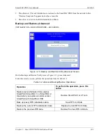
Page 98: ...wing the instructions in the window and press ENTER You are returned to the Set Passwords Menu BACKUP RESTORE INITIALIZATION BACKUP RESTORE Figure 3 11 Backup and Restore Utility Screen This feature enables you to back up and restore tools programmed on your SmartPAC PRO Tools may be backed up to a network drive or if you have ordered the USB Backup Restore option to a USB disk inserted in the Sma...

Page 99: ...tor on the SmartPAC PRO s front panel 2 Select the BACKUP RESTORE item on the Main Initialization Menu The Backup and Restore Utility screen appears Figure 3 11 The date of the last backup if one was performed is displayed on the screen 3 For Target Location select USB Disk 4 Press Backup and follow the instructions on the screen Backing Up Tools to a Network Folder 1 Set up a folder for backup re...

Page 100: ... Insert the USB disk containing the tools backup into the USB connector 2 Select the BACKUP RESTORE item on the Main Initialization Menu The Backup and Restore Utility screen appears The date of the last backup if one was performed is displayed on the screen 3 Press Restore When the operation is done Restore Completed appears below the screen title 4 Press Exit to return to the Main Initialization...

Page 101: ...een On the Backup and Restore Utility screen Figure 3 11 press Advanced From this screen you can perform the operations listed in Table 3 2 Table 3 2 Advanced Backup Restore Operations Operation To perform the operation press this button Restore tools information from original SmartPAC SmartPAC 1 or SmartPAC 2 Used when you replace an older version SmartPAC with SmartPAC PRO Restore SmartPAC1 or 2...

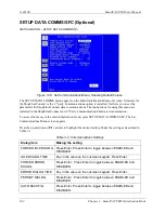
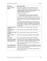
Page 102: ...umentation To access the menu in the main initialization menu press SETUP DATA COMMS SFC The Set Communications Menu screen appears Press the up and down arrows to highlight the desired setting Make the setting as described in Table 3 3 Table 3 3 Communications Settings Dialog item Making the setting FORCED IDLE DIALOG Press Enter Press Enter to toggle between ENABLED and DISABLED IDLE DIALOG TIME...

Page 103: ...ng is selected the SET SPECIAL NAMES and SET CANNED NAMES items do not display UNPLANNED RESET STROKES Key in the value on the onscreen keypad Press Enter PLANNED RESET STROKES Key in the value on the onscreen keypad Press Enter CHANGEOVER RESET STROKES Key in the value on the onscreen keypad Press Enter SINGLE STROKE MODE Press Enter to toggle between ENABLED and DISABLED IDLE TIMER Key in the va...

Page 104: ...e 16 canned names Figure 3 15 Set Communications Menu Dialog Screen Mode 16 16 On the Set Communications Menu screen set DIALOG SCREEN MODE to 16 16 1 Press the arrows to select SET SPECIAL NAMES 2 Press ENTER The Dialog Special Name Choice Menu screen appears 3 Press the arrows to select a special name 1 16 4 Press the arrows to highlight the name or sequence number 5 Press ENTER Key in the name ...

Page 105: ...ION SETUP DATA COMMS SFC SET CANNED NAMES Figure 3 17 Dialog Fixed Name Choice Menu You can enter numbers to indicate the order in which the canned predetermined names show up on the dialog menu 1 Press the arrows to select SET CANNED NAMES 2 Press ENTER The Dialog Fixed Name Choice Menu screen appears 3 Press the arrows to highlight the number next to a canned name on the list ...

Page 106: ...SmartPAC PRO to your network before you can use e mail messaging or SmartView remote viewing utility For e mail your network must have a valid SMTP mail server If your network requires static IP addresses your network administrator should call Wintriss Tech Support The SETUP NETWORK item on the Main Initialization Menu allows you to set up SmartPAC PRO s E mail and SmartView functions and to make ...

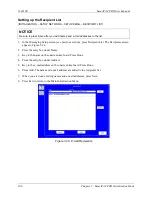
Page 107: ... network contact your IT department 1 Press SETUP NETWORK on the Main Initialization Menu The Network Setup Utility screen appears 2 Press the checkbox next to ENABLE EMAIL so it is check marked 3 Press SETUP EMAIL The Messaging Setup screen appears 4 Press each entry box and key in the information using the onscreen keyboard For secure login with user name and password check the box next to Secur...

Page 108: ...vious section press Recipient List The Recipients screen appears Figure 3 20 2 Press the entry box under Name 3 Key in the name on the onscreen keyboard Press Done 4 Press the entry box under Address 5 Key in the e mail address on the onscreen keyboard Press Done 6 Press Add The name and e mail address are added to the recipients list 7 When you are done entering names and e mail addresses press S...

Page 109: ...Messages Screen 1 In the Messaging Setup screen see SETUP EMAIL page 107 press Message List The Predefined Messages screen appears Figure 3 21 2 Press the entry box under Message 3 Key in the message on the onscreen keyboard Then press Done 4 Press Add The message is added to the recipients list 5 When you are done entering names and e mail addresses press Save 6 Press Exit to return to the Main I...

Page 110: ...r Setup screen that appears Press each entry box and key in the information on the onscreen keyboard Press Done 4 When finished press Apply Changes Press Exit to return to the Network Setup Utility screen SMARTVIEW FUNCTION INITIALIZATION SETUP NETWORK ENABLE SMARTVIEW SmartPAC PRO s SmartView function enables individuals on your network to remotely view the status of each press If you plan to use...

Page 111: ...ess type do the following 1 Press the button next to PRESS TYPE to toggle between STRAIGHT SIDE and GAP FRAME 2 When finished on this screen press Back to return to the Main Initialization Menu REMOTE ADMIN SETTINGS INITIALIZATION SETUP NETWORK REMOTE ADMIN SETTINGS Figure 3 23 Remote Admin Settings Screen 1 In the Network Setup Utility screen press REMOTE ADMIN SETTINGS The Remote Admin Settings ...

Page 112: ...xt to Prohibit Any Fault Reset see previous section you can select faults to prohibit from remote reset 1 In the Remote Admin Settings screen press the Fault Reset tab A list of faults appears with a checkbox next to each 2 Press to check the boxes of the faults to prohibit from remote reset To see additional faults scroll down using the scroll bar at the right of the list 3 When finished press Ap...

Page 113: ... Network Settings Local Area Connection screen appears Network Setting Comment Connection Status Indicates whether SmartPAC PRO is connected to the network Address Type Press in the entry box to toggle between DHCP and Static IP Address Press in the entry box and key in the IP address Press Enter when done Subnet Mask Press in the entry box and key in the subnet mask Press Enter when done Default ...

Page 114: ...e working with Wintriss Tech Support for initial setup or troubleshooting Figure 3 26 Diagnostics Menu This section documents only the following items COMMUNICATIONS which allows you to run a communications loopback test SET CLOCK which allows you to set SmartPAC PRO s internal clock to local time SAVE TO USB DISK which allows you to save screen captures and other items to a USB disk UPDATE FIRMWA...

Page 115: ...nsmit data displayed as blue on a white background and Receive data displayed as white on blue This view shows the data as it is transmitted and received in real time Press RESET BUFFER to view the data starting at the beginning of the buffer In the split view Transmit data is shown in the upper half of the screen Receive data in the lower half In this view the data is always shown starting at the...

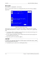
Page 116: ...ormat i e 1 30 p m 13 30 11 00 p m 23 00 To do so perform these steps 1 Press the arrows to highlight the segment of the date or time that you want to change then press ENTER The On screen keyboard displays 2 Key in a value and press ENTER You are returned to the Set the Clock screen showing the date or time segment you selected in step 1 3 Repeat steps 1 and 2 for other date time segments NOTICE ...

Page 117: ...e following 1 Make sure a USB disk is installed in the USB connector on the SmartPAC PRO s front panel 2 Access the Main Initialization Menu select DIAGNOSTICS and when the Diagnostics Menu displays select SAVE TO USB DISK The following messages appear in succession PLEASE WAIT WHILE THE DATA IS BEING TRANSFERRED TO THE USB DISK THIS MAY TAKE UP TO ONE MINUTE TO COMPLETE THE USB DISK TRANSFER HAS ...

Page 118: ... favorites and or screen captures Disable Loss Rotation page 122 Reset Initialization Data INITIALIZATION SYSTEM INIT RESET INITIALIZATION DATA Select Modules to Initialize to clear data To clear initialization data from SmartPAC PRO follow these steps 1 In the Initialization screen press SYSTEM INIT The Initialize SmartPAC System screen appears Figure 3 27 2 Press RESET INITIALIZATION DATA the Mo...

Page 119: ... orange and is labeled Module Name included Figure 3 29 This means the module s data will be cleared If you do not want to clear this module s data press Cancel Figure 3 29 Modules Press Control Selected 5 After you have selected the modules you want cleared in addition to SmartPAC initialization data press OK A warning window appears Figure 3 30 6 Press OK to clear the initialization data To exit...

Page 120: ...n use the Application Data Menu 1 In the Initialize SmartPAC System screen Figure 3 27 page 118 press Application Data Menu The Application Data Menu screen appears Figure 3 31 2 Press the Tools Tab 3 Press the box for each tool you want to delete check marking it To select all the tools press the box next to Select All 4 Press Delete Selected Tools A warning box appears Figure 3 32 If you want to...

Page 121: ...TAB 1 In the Initialize SmartPAC System screen Figure 3 27 page 118 press Application Data Menu The Application Data Menu screen appears Figure 3 31 2 Press the Config Tab Figure 3 33 Figure 3 33 Application Data Menu Configuration 3 To delete all dashboards favorites or screen captures press the appropriate button A warning box appears If you want to delete the items press Yes If you do not want ...

Page 122: ...ION refer to Setting Link Motion below If press speed does not vary during the stroke leave RESOLVER MOTION MODE set to NORMAL MOTION and install and zero the resolver so that bottom dead center equals 180 This setting will likely result in a top dead center reading of less than 360 but this value is acceptable in these circumstances Refer to Chapter 2 for instructions on installing and zeroing th...

Page 123: ...ion Menu and select FEED CONTROL 2 On the Feed Control screen that displays select SETTLING TIME and set it to 30 mS 3 Switch to Program Mode select the tool that is currently loaded then on the Tool Programming Menu select FEED CONTROL see Changing Settings for a Loaded Tool page 130 4 On the Servo Feed Parameters screen select FEED ADVISOR then on the Servo Feed Advisor screen select CALCULATE 5...

Page 124: ...hen you have changed the PRESS SPEED value select CALCULATE 4 Press Exit to return to the Tool Programming Menu then load the tool Cycle the press and notice whether feeding is complete at the correct time If feeding is complete at the correct time you are finished with press speed compensation for link motion If feeding is completed too late switch to Program Mode increase Press Speed in the Feed...

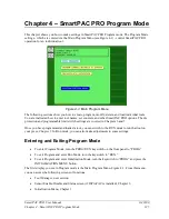
Page 125: ...tch settings are covered in Chapters 6 and 7 Once you have programmed and loaded a tool you can switch to the RUN mode to run that tool on your press Chapter 5 In Run mode you can also make adjustments to some settings Entering and Exiting Program Mode To enter Program Mode turn the PROG RUN keyswitch on the front panel to PROG To exit Program and enter Run Mode turn the keyswitch to RUN To exit P...

Page 126: ...eady been created The currently loaded tool is highlighted To view edit load delete create or copy a tool press the appropriate button see detailed instructions in the sections below Figure 4 2 Tool Manager Screen Tool Manager List View For more detail about the tools press List View to show the information in Figure 4 3 The currently loaded tool is highlighted in yellow Sort the tools by number n...

Page 127: ...ser Manual 1143100 Chapter 4 SmartPAC PRO Program Mode 127 Figure 4 3 Tool Manager List View Figure 4 4 Tool Manager List View Tool Detail Loaded tool highlighted in yellow detail shown for tool highlighted in green ...

Page 128: ...te a setup for a new tool do the following 1 On the Tool Manager screen press New Tool The Numeric Entry keypad displays Figure 4 5 2 Key in desired tool number and press ENTER Please note that tool numbers cannot be duplicated 3 The new tool will now appear in the Tool Manager but will have no settings associated with it Before you can load and run this setup you must program settings for this to...

Page 129: ...er Figure 4 6 Copying an Existing Tool 4 The newly copied tool will now appear in the Tool Manager Before you run it you will need to edit the settings unique to this tool See Tool Program Menu page 133 Copying Tool Template to a New Tool PROGRAM TOOL MANAGER Select Tool Template 9999999 COPY TOOL Tool Template which is assigned tool number 9999999 is a tool you can program with settings common to...

Page 130: ...ons for correcting the problem If the error is not covered in Chapter 8 or you cannot fix the problem call Wintriss Tech Support Changing Settings for a Loaded Tool PROGRAM TOOL MANAGER Select Tool EDIT TOOL To change settings for a loaded tool do the following 1 With the currently loaded tool highlighted on the Tool Manager screen press the EDIT TOOL button The Tool Program menu is displayed To C...

Page 131: ...ue the deletion process A message displays indicating that the tool has been deleted and you are returned to the Tool Manager screen with the deleted tool removed Viewing Tool Data Summary PROGRAM TOOL MANAGER Select Tool VIEW TOOL SUMMARY Figure 4 9 Tool Data Summary Screen 1 To see a summary of the tool data in the Tool Manager screen Figure 4 2 press View Tool Summary The Tool Data Summary scre...

Page 132: ...Bottom At the bottom of the screen to which you may need to scroll down you can enter additional information in the Tool Notes area Figure 4 10 1 Touch inside the Tool Note are and the on screen keyboard appears 2 Key in the desired information 3 Press Done Saving Tool Data Summary to USB Disk To save the tool data summary on a USB disk 1 Insert a USB disk into the SmartPAC PRO s USB connector 2 S...

Page 133: ...different The following sections show you how to make settings for each of the items on the menu NOTICE RELOAD CURRENTLY LOADED TOOL IF YOU CHANGE IT If you change settings for a tool that is currently loaded you should load the tool again after you make the settings If you do not re load the tool the old settings will be used TOOL NAME PROGRAM TOOL MANAGER Select Tool EDIT TOOL TOOL NAME This ite...

Page 134: ...am menu COUNTERS PROGRAM TOOL MANAGER Select Tool EDIT TOOL COUNTERS The counters maintain counts of press cycles strokes good parts and the total number hits on each die that is run in the press Secondary counters called Batch Counters can initiate various actions when a preset number of strokes has been reached Settings are made via the Counters screen Figure 4 13 Figure 4 13 Counters Screen ...

Page 135: ...d and rerun again at a later date Batch counters There are three Batch Counters which can be selectively incremented by either the Strokes or Good Parts counter Each batch counter can be set to initiate one of three actions when the programmed preset is reached Top Stop Toggle or Pulse When a Batch counter is set to TOP STOP SmartPAC PRO top stops the press and displays a message as it does for St...

Page 136: ...you entered displays in the PRESET VALUE field you selected Setting the preset to 0 disables the output function top stop toggle or pulse for the counter 4 Repeat steps 2 and 3 for each counter preset you want to program Changing Count Values Under some circumstances you may need to adjust the count upward or downward or you may want to start the count at some value other than zero To change count...

Page 137: ...lt output mode is set to TOP STOP increment mode to STROKE To change these settings perform the following steps NOTICE PULSE and TOGGLE settings are available only when ProCamPAC is an installed option If you attempt to make these settings when your system does not have a programmable cam SmartPAC PRO will display a message indicating that the settings are not available See Chapter 7 for informati...

Page 138: ...ounter Mode Selections screen allows you to set a common increment angle for Strokes Good Parts and Batch 1 counters and separate increment angles for Batch 2 and Batch 3 counters To change default increment angles do the following 1 On the Counter Mode Selections screen move the highlight bar to the increment angle value for the counter you want to adjust e g Batch 2 then press ENTER The Numeric ...

Page 139: ...n This pre load value displays in the COUNT field for each Batch counter you specify decreasing by that value the number of strokes or good parts required to reach the preset value You can reset these pre load values in Run mode when the Batch preset is reached see COUNTERS page 147 as long as you set the CHANGE COUNTS parameter on the Security Access Menu in Initialization to PROGRAM AND RUN MODE...

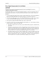
Page 140: ... limits apply to all operating modes Continuous Single stroke and Inch When the speed of the press exceeds the maximum limit SmartPAC PRO stops the press and displays the fault message Maximum press speed exceeded When press speed drops below the minimum limit SmartPAC PRO stops the press and displays the fault message Minimum press speed exceeded These fault message are documented in Chapter 8 Yo...

Page 141: ...Select the MINIMUM PRESS SPEED value and key in your entry in the Numeric Entry window When the window closes your entry appears in the MINIMUM PRESS SPEED field 5 When you are finished press EXIT to return to the Tool Program Menu TOOL INFORMATION PROGRAM TOOL MANAGER Select Tool EDIT TOOL TOOL INFORMATION The Tool Information screen allows you to enter up to six parameters and up to two lines of...

Page 142: ...1143100 SmartPAC PRO User Manual 142 Chapter 4 SmartPAC PRO Program Mode ...

Page 143: ...90 Stop time Test 150 Calculating the Safety Distance 150 PRESS SPEED 151 TOOL INFORMATION 153 ERROR EVENT LOG 153 LOAD NEW TOOL 154 MESSAGING 156 Selecting Recipients 156 Selecting Message 157 Selecting Attachments 158 Sending the Message 158 This chapter shows you how to use the SmartPAC PRO in the Run mode which is the mode you select to run production Instructions include how to adjust setting...

Page 144: ...settings or loading tool numbers you can lock out choices on the Run menu or require a password for access See SECURITY ACCESS page 94 The following sections show you how to load a tool adjust counters and speed settings for the tool perform the 90 stop time test to determine the longest stopping time of the press and view tool information and the error log The chapter also covers enabling and dis...

Page 145: ... you are prevented from gaining access to that item No message is displayed to indicate that the setting is locked but when you press ENTER to access the item or press the arrows to make an adjustment nothing happens When the LOAD NEW TOOL item is locked out that entry does not appear on the Main Run Menu Displaying Multiple Faults Whenever more than one fault occurs in response to a press conditi...

Page 146: ...ensors disabled output that turns on when the sensors are disabled See Chapter 2 for installation details NOTICE If you temporarily disable sensors be sure to re enable them before you resume making parts In the Main Run screen the top button enables or disables sensors If it is labeled DISABLE SENSORS press to enable sensors If it is labeled ENABLE SENSORS press to disable sensors When sensors ar...

Page 147: ...hits counters and presets if you have the appropriate security access For instructions on entering counter and preset values see COUNTERS page 134 If you have set the CHANGE COUNTS parameter on the Security Access Menu in Initialization to PROGRAM AND RUN MODES see SECURITY ACCESS page 94 you can reset batch counts to the values you have programmed for batch pre loads see Setting Batch Pre Load Co...

Page 148: ...me limit see Performing the 90 Stop time Test page 150 Recalculate the safety distance based on the new stop time limit and adjust or reinstall safeguarding devices according to the new safety distance Failure to comply with these instructions will result in death or serious injury SmartPAC PRO s built in Brake Monitor enables you to view your press s starting time stopping time and stopping angle...

Page 149: ...e stopping angle value helps you when you set up the top stop cam For example if the stopping angle is 100 you would set the top stop cam to turn on at 260 Determining the Stopping Time of Your Press You need to determine the stopping time of your press at Top Stop in order to calculate the stop time limit to set in Initialization To do so perform the following steps 1 Install the heaviest upper d...

Page 150: ...me test The following message displays at the bottom of the screen 90 DEGREE BRAKE TEST ARMED PRESS EXIT TO CANCEL TEST 5 When SmartPAC PRO emergency stops the press which occurs the next time the press reaches 90 record the number in the 90 STOP TIME VALUE MSEC field on the Stop Time Status screen 6 Repeat the test at least 5 more times 7 Record the highest reading from all your tests This is the...

Page 151: ...mits apply to all Run operating modes Continuous Single stroke and Inch Adjustments are made on the Press Speed Parameters screen shown in Figure 5 7 Figure 5 7 Press Speed Parameters Screen When the speed of the press exceeds the maximum speed limit SmartPAC PRO stops the press and displays the fault message Maximum press speed exceeded When press speed drops below the minimum speed limit SmartPA...

Page 152: ...alue you enter in the MAXIMUM PRESS SPEED field must be greater than the Minimum Press Speed value If the Maximum Speed setting is less than or equal to the Minimum Speed value SmartPAC PRO changes the Maximum Speed to one Stroke per Minute greater than the Minimum Speed To disable speed control set both Maximum and Minimum Speed values to zero 0 3 Key in a new value following the directions in th...

Page 153: ...ess is stopped due to a fault the log records the error message which gives the reason for the stop and the stroke count and crankshaft angle at which the stop occurred When a new tool is loaded the log displays the tool number If SmartPAC PRO is connected to a computer network and e mail is enabled the log also shows messages sent by SmartPAC PRO When SmartPAC PRO is networked you can send the Er...

Page 154: ...EW TOOL does not appear on the Main Run Menu if LOAD TOOL has been set to PROGRAM MODE ONLY on the Security Access Menu in Initialization mode See SECURITY ACCESS page 94 The LOAD NEW TOOL menu selection enables you to load a new tool when the press is stopped You cannot load a new tool when the press is running If you attempt to do so SmartPAC PRO will display an error message indicating that the...

Page 155: ...ess LOAD TOOL A warning window displays Figure 5 11 Figure 5 11 Load Tool Warning Window 3 Press OK A message displays indicating that the tool is being loaded then you are returned to the Main Run Menu with the tool you loaded shown in the Status Box NOTICE If an error message displays go to Chapter 8 and follow the instructions for correcting the problem If the error is not covered in Chapter 8 ...

Page 156: ...ddresses and predefined messages in Initialization under SETUP NETWORK See SETUP EMAIL page 107 Selecting Recipients 1 On the Run menu press Messaging The Messaging screen appears Figure 5 12 If you want to stay in the Messaging screen after sending uncheck the box labeled Exit after send Figure 5 13 Select Recipients 2 Press To The Select Recipients window opens Figure 5 13 ...

Page 157: ...t Message Window 5 Press Select Message The Select Message screen appears Figure 5 14 6 Press the desired message to select it or press Custom Message to key in a different message 7 Press okay If you selected a predefined message you are returned to the Messaging screen If you selected Custom Message key in the message on the onscreen keyboard and press Done to return to the Messaging screen Then...

Page 158: ...ss Attach A window opens showing the available files 9 Press the file you want to attach 10 Press okay Sending the Message Figure 5 16 Sending the Message When you finish preparing the message press the send button that shows an envelope and an arrow circled in Figure 5 16 A message displays Please wait sending After sending is complete Send Success appears A message sent to This Press appears as ...

Page 159: ...Red Sensors 169 Yellow Sensors 169 Red Sensors 169 Auto Reset Static Sensors 169 Bypass Angle Static Sensors 170 MINIMUM ACTUATION TIME Static Sensors 171 Cyclic Sensors Green Sensors 171 Standard Green Sensors 172 Green Quick Check Sensors 173 Green Constant Sensors 173 Green Special Sensors 174 Green Flex Sensors 175 Masking 176 Programming Sensor Settings 177 Setting Enable Mode 177 COPY A SENS...

Page 160: ...ded in your system If you ordered SmartPAC PRO with other optional modules such as AutoSetPAC load monitor or ProPAC process monitor refer to the user manual for that option for complete details on its installation and use NOTE ADDED FEATURES FOR DIPROPAC Unlimited number of custom names able to be set in Program mode Tool enable mode for each tool can be set in Program mode Changes to red and yel...

Page 161: ...l or it can be on a global name list available to all tools See Table 6 1 and Entering Global Sensor Names page 162 The preset sensor names are UNNAMED AIR PRESSURE END OF STOCK MATERIAL BUCKLE MISFEED MISFEED PILOT OVER FEED PART EJECTION SHORT FEED SLUG DETECTION STRIPPER CYLINDER RETURN Table 6 1 Sensor Names Preset names Custom name global Custom name individual Use when programming any sensor...

Page 162: ...names used only with individual tools or add them to the global sensor name list See Naming the Sensor page179 To enter the global sensor names in Initialization mode follow the instructions below Figure 6 1 Main Initialization Menu 1 In the Main Initialization Menu press GLOBAL SENSOR NAMES The Global Sensor Names screen appears If no global sensor names have been entered the screen looks like Fi...

Page 163: ...r name press NEW ENTRY An entry keyboard appears Figure 6 3 Figure 6 3 Entry Keyboard for Global Sensor Name 3 Key in the sensor name you want as in Figure 6 4 Press Enter when done The Global Sensor Names screen appears showing the name you added Figure 6 5 Figure 6 4 Entry Keyboard Showing New Global Sensor Name ...

Page 164: ...r 32 SENSOR ENABLE MODE SENSOR ENABLE MODE allows you to select the way in which your die protection sensors are enabled This item also allows you to enable Setup mode if this feature has been wired during installation You make these settings on the Die Protection Mode Selection Menu Figure 6 6 You can later change the sensor enable mode for any tool in Program mode Selecting Sensor Enable Mode by...

Page 165: ...to allow after the press is restarted before DiProPAC re enables that sensor see Setting the Stroke Count for Auto Enable by Sensor page 183 To select a Sensor Enable mode do the following 1 Press SENSOR ENABLE MODE on the Main Initialization Menu The Die Protection Mode Selection Menu appears Figure 6 6 2 Press the SENSOR ENABLE MODE item repeatedly until the setting you want is displayed then pr...

Page 166: ...am Menu only when DiProPAC is installed It enables you to program up to 8 16 or 32 die protection sensors You make settings via the Die Protection Sensor Menu Figure 6 8 When this screen opens it shows eight or sixteen sensors If you have a 32 sensor unit press NEXT SENSOR GROUP to open a new screen showing the additional sensors Figure 6 8 Die Protection Sensor Menu for Tool 1063 Sensors 1 16 DiP...

Page 167: ...nitialization SENSOR ENABLE MODE page 164 applies to all the sensors on all the tools If you want to change the enable mode for one or more tools you can do so in Program mode Follow the instructions below 1 In the Die Protection Program screen for the desired tool Figure 6 10 press the SENSOR ENABLE MODE item repeatedly until AUTO BY TOOL appears 2 To change the number of strokes for auto enable ...

Page 168: ... when to expect that sensor to actuate If the event doesn t occur during this Ready Signal the SmartPAC PRO stops the press You set a Ready signal only for green sensors which monitor events that must occur on every stroke Sensor Types NOTICE For more detailed information on Sensor Types visit https wintriss com wcg knowledgebase dieprotection html Sensors used with die protection systems are clas...

Page 169: ... sensors are ON and the press is allowed to run However each time the operator removes the finished part a fault occurs requiring the operator to reset the error on every stroke This isn t really an error it s a normal part of the operation For such applications an Auto Reset function has been added to the static sensors When Auto Reset is enabled for a sensor the error is automatically cleared wh...

Page 170: ...e optional Bypass Angle for Yellow and Red sensors During the bypass SmartPAC PRO ignores the sensor so any fault during that window will not cause a nuisance stop During the rest of the stroke SmartPAC PRO monitors the sensor normally To set the Bypass Angle follow these steps 1 In the Sensor Program Screen Figure 6 11 press the ADD button for BYPASS ANGLE The Bypass Angle screen appears 2 Use on...

Page 171: ...aults on static sensors at random times during the stroke use the Minimum Actuation Time setting This feature enables the DiProPAC to ignore short actuations of static sensors but will stop the press when a fault persists for longer than the specified minimum actuation time The value can be set from 10 to 2500 ms The default value is 0 which turns this feature off Set the Minimum Actuation Time in...

Page 172: ... most of these green sensors Masking page 176 NOTICE SETTING INDEPENDENT READY SIGNALS FOR GREEN SENSORS Previous versions of SmartPAC PRO placed limitations on the setting of ready signals for sensors 17 32 This is no longer the case You can give each sensor a different ready signal if you like Standard Green Sensors A standard green sensor must turn on at least momentarily at some point during t...

Page 173: ...s the sensor must turn on and turn off within the Ready signal Figure 6 14 Ready Signal Programming for a Green Quick Check Sensor Green Constant Sensors When you set a sensor input to green constant the sensor must turn on before the Ready signal begins and turn off after the Ready signal ends remaining actuated continuously during the entire Ready signal Figure 6 15 Ready Signal Programming for ...

Page 174: ...n make without the sensor actuating If needed you can also set a number of strokes to elapse before the green special starts its first monitoring cycle For example if your die clears the slugs from a particular ejection hole approximately every four strokes set a Green Special sensor input for a five stroke window If no slugs are ejected after five strokes SmartPAC PRO sends a Stop command to the ...

Page 175: ...ified The masking feature is included Masking page 176 Examples of how to use the Green Flex sensor Feed detection on a higher speed press In this case the end of the ready signal is used to verify that the strip has fully fed and the start of the ready signal is used to detect feed slippage at the start of the feed on the next cycle Using the Green Flex sensor type set it so the sensor Must be OF...

Page 176: ...ng feature might be used A part requires four press cycles to be produced On the fourth cycle a cutoff punch is gagged in and the finished part is cut off the strip and falls onto a conveyor The part ejection sensor detects the part as it drops onto the conveyor during the upstroke If an unmasked standard Green sensor type is used for this application it would generate an error on three out of fou...

Page 177: ...reen Sensor Type with Masking Enabled This sensor will check for part ejection every fourth stroke Programming Sensor Settings Setting Enable Mode In initialization you may have set a global enable mode that applies to all tools Entering Global Sensor Names page 162 In Program mode you can change it for each tool if you want The options are MANUAL ENABLE You manually enable sensors in Run mode ...

Page 178: ... you program each sensor enter a number of strokes into the AUTO ENABLE COUNTER for each it If you do not enter a number of strokes the auto enable count defaults to zero COPY A SENSOR To program a sensor first you select the input then name the sensor then select the sensor type There is now a COPY SENSOR function button on the sensor type selection screen When selected a list of previously progr...

Page 179: ...sensor program settings Assign a name to each sensor and enter custom sensors page 179 Setting the Auto Enable by Tool Counter Value page 182 or Setting the Stroke Count for Auto Enable by Sensor page 183 Set the sensor type i e red yellow green etc page 184 Set stop type i e Emergency Stop Top Stop and Smart Stop page 185 Set the critical angle for a sensor programmed as Smart Stop page 186 Set t...

Page 180: ... Sensor number you want to program A list of names appears including the preset names and any global sensor names you have previously entered Entering Global Sensor Names page 162 Use the scroll bar at right to move up and down the list If you want to use one of those names press it The sensor type screen appears Go to Setting Sensor Type page 184 If you want to enter a new sensor name press NEW E...

Page 181: ... Enter A confirmation window opens Figure 6 25 Figure 6 24 New Sensor Name Entry Keyboard 6 The confirmation window asks if you would like to add the new name to the global sensor name list If you want to add it to the list press YES If you do not want to add it to the list press NO Figure 6 25 Confirmation Window for Adding Name to Global List ...

Page 182: ...ROTECTION on the Tool Program Menu The Die Protection Sensor Menu displays page Figure 6 26 with the AUTO ENABLE COUNTER field at lower left of the screen Figure 6 26 Die Protection Sensor Menu with Auto Enable by Tool Counter 2 Select the AUTO ENABLE COUNTER field The Numeric Entry window displays 3 Key in the value you want maximum is 99 and press ENTER The value displays in the AUTO ENABLE COUN...

Page 183: ...uto Enable by Sensor Stroke Count screen displays Figure 6 28 Figure 6 28 Auto Enable by Sensor Stroke Count Screen This screen allows you to set the Auto Enable by Sensor counter which specifies the number of press strokes necessary to re enable the sensor following a DISABLE SENSORS command See SENSOR ENABLE DISABLE STATUS page 192 and DISABLE ENABLE SENSORS page 194 To set the Auto Enable by Se...

Page 184: ... 29 displays with the name you selected for the sensor shown at the right of the Status Box beneath the sensor number Figure 6 29 Sensor Type Screen You can select one of six types of sensor see Setting Sensor Type page 184 for details or you can select NOT USED in which case that sensor is not programmed for the tool To set the sensor type do the following Press to select the sensor type you want...

Page 185: ...n the next stroke before the die closes Top Stop SmartPAC PRO stops the press at the top of its stroke after a sensor fault is detected You should use this setting for events that do not threaten the die or that occur between the critical angle and bottom dead center BDC A typical Top Stop application is a sensor that monitors a feed like a roll feed that takes place well into the downstroke Setti...

Page 186: ... are finished and the Sensor Settings screen displays on which all your programmed sensor settings are shown see Viewing and Changing Sensor Settings page 190 Setting the Critical Angle for a Sensor Set to SMART STOP When you program a sensor for a Smart Stop you must also set the critical angle SmartPAC PRO uses to determine whether an Emergency Stop or Top Stop command is sent to the press The c...

Page 187: ...u to enter a different value After you have programmed one or more Smart Stop sensors you can change the critical angle by performing these steps 1 On the Die Protection Sensor Menu select a sensor programmed as Smart Stop The Sensor Settings screen displays Figure 6 27 page 183 2 Select SMART STOP The Sensor Stop Type screen displays with SMART STOP highlighted 3 Press Set Critical Angle to displ...

Page 188: ...us and minus buttons or the buttons labelled SET ANGLE ON and SET ANGLE OFF as follows 1 Set the Ready On angle Press the plus and minus buttons to adjust on angle shown inside the clock display circle to the desired value OR Press SET ON ANGLE A numeric entry window opens Key in the desired ON angle and press Enter 2 Set the Ready OFF angle in a similar way 3 When you have finished setting the Re...

Page 189: ...or Stroke Count Screen NOTICE For more information about Green Special sensors refer to Understanding Sensor Terminology page 168 To set the Green Special sensor stroke count do the following 1 Press the box next to the word STROKES A numeric entry window appears 2 Key in the desired stroke count maximum value is 99 Press Enter 3 Press Back The Sensor Program screen displays Figure 6 27 page 183 s...

Page 190: ...or on the Die Protection Sensor Menu To change sensor settings do the following 1 On the Die Protection Sensor menu Figure 6 27 press the setting you want to change The screen on which that setting is programmed displays For example if you select the SENSOR NAME setting the Sensor Name List screen displays Figure 6 23 page 180 2 Change the setting on the displayed screen and press back when you ar...

Page 191: ...pe stop type and the Ready signal On and Off angles if applicable for all of the programmed sensors It also shows the stroke count for green special and the number of strokes during the ready angle for green flex Figure 6 35 Sensor Summary Screen Deleting a Sensor To delete a Die Protection sensor do the following 1 On the Die Protection Sensor Menu select the sensor you want to delete The Sensor ...

Page 192: ... Figure 6 36 Figure 6 36 Sensor On Off Status Viewing Sensor Status To view the status of your sensors do the following 1 Press SENSOR ENABLE DISABLE STATUS on the Main Program Menu The Sensor On Off Status screen displays showing status settings for sensors 1 through 8 or 1 through 16 Sensors may have one of three status settings OFF ON or N U Not Used 2 To view sensors 17 through 32 if a 32 sens...

Page 193: ...elled ENABLE ALL SENSORS Press that button to enable or disable all sensors NOTICE You can also enable or disable all sensors in Run mode See DISABLE ENABLE SENSORS page 194 Turning a Sensor Off or On To turn a selected sensor Off or On do the following 1 On the Sensor On Off Status screen highlight the sensor you want 2 Press ENTER to toggle between the OFF and ON settings until the setting you w...

Page 194: ...ain Run Menu with SENSORS DISABLED in the status bar and ENABLE SENSORS on the menu To disable or enable sensors do the following 4 Press DISABLE SENSORS or ENABLE SENSORS item on the Main Run Menu If you are enabling sensors the message at the left of the Status Box changes from SENSORS DISABLED to SENSORS ENABLED If you are disabling sensors the confirmation window shown in Figure 6 39 displays ...

Page 195: ...rarily disable sensors be sure to re enable them before you resume making parts NOTICE For help with the Die Protection Menu and the screens accessible from it press the key when the applicable screen is displayed The Die Protection selection on the Main Run Menu appears only when a DiProPAC module is installed It allows you to view the status of your die protection sensors and to adjust the Ready...

Page 196: ...in Figure 6 41 displays Figure 6 41 Ready Signal Programming Screen The functionality of this screen differs slightly from that of the Ready Signal Programming screen in Program mode When you run the press the angles at which the selected sensor turns on and off during each stroke are shown in the window labeled SENSOR at the right of the screen and the number of degrees that the sensor is on is r...

Page 197: ...ed the Sensor window displays zeros If the press is running SmartPAC PRO displays the actuation angles for the next stroke NOTICE Pressing the Update the Sensor Arc button may not properly update sensor actuations when you are using a mechanical sensor which vibrates constantly during the stroke It is better to use an electronic sensor that is not prone to constant contact bounce Pressing CHG REFE...

Page 198: ...n Special Sensors To adjust the green special sensor preset value for press strokes do the following 1 On the Die Protection Menu select the desired Green Special sensor The Green Special Sensor Stroke Count screen displays This screen is identical to the Green Special Sensor Stroke Count screen in Program mode see Chapter 5 except that it displays additional information in the Status box 2 Press ...

Page 199: ...he sensor block is blue the sensor is actuated If it is white the sensor is not actuated The Sensor Status screen is designed so that you can quickly check the status of all your sensors When you select the screen with the press running the actuation blocks for green sensors will flash as they actuate once every stroke You might not see this on every stroke if the press speed is faster than the sc...

Page 200: ...1143100 SmartPAC PRO User Manual 200 Chapter 6 Using DiProPAC Die Protection Optional ...

Page 201: ...Mode CAM SWITCH ProCamPAC 218 Viewing Cam Timing 220 Viewing the Global Cam Summary 221 Viewing the Cam Summary 221 NOTICE OPTIONAL MODULES PROCAMPAC AND DIPROPAC INCLUDED IN MANUAL When you order your SmartPAC PRO you may include the DiProPAC die protection and or ProCamPAC programmable cam switch option This manual includes instructions for installing and using both modules Remember that they ar...

Page 202: ...e AC power supply wires to SmartPAC PRO should be run separately from the DC control wires going to the ProCamPAC Output Assembly Never use the SmartPAC PRO power terminals as a junction point to provide power for external devices In most cases the AC power supply wires should be connected directly to the press control cabinet Do not use the ProCam output enclosure as a junction box for the AC con...

Page 203: ... additional names Figure 7 2 Cam Channel Name Selection Screen 3 Press the name that best describes the function of the selected cam channel You are returned to the Cam Channel Name Menu with the name you selected displayed for the selected channel If you want to add a different cam channel name press CUSTOM NAME on the names list The on screen keyboard appears Key in the custom name and press ENT...

Page 204: ... thousand strokes per minute SPM A channel programmed as Auto Advance automatically advances cam timing as the speed of the press increases and delays the timing as speed decreases The rate of advance or delay is controlled by an advance constant a specified number of degrees of advance for each 100 SPM increase in press speed You can set two advance constants on the Auto Advance Menu Advance Cons...

Page 205: ...he angle For instance if the press stops at 12 the stopping angle is actually 12 360 or 372 3 Subtract the two angle values We will call this result Ac Aa Ab Ac 4 Subtract the two press speeds We will call this result RPMc RPMa RPMb RPMc 5 Divide Ac the difference between the angles by RPMc the difference between the press speeds and multiply that value by 100 That is the number of degrees per 100...

Page 206: ...LE CAM SWITCH NOT FOR SAFETY USE Use SmartPAC PRO s programmable cam switch to control auxiliary functions only The SmartPAC PRO programmable cam capability should never be used to provide timing signals for any safety use including clutch brake control or muting of light curtains Failure to comply with these instructions will result in death or serious injury This item which appears on the Main I...

Page 207: ... Select the cam you want to program The Global Cam Timing Type screen displays Figure 7 5 Figure 7 5 Global Cam Timing Type Screen 2 Select the type of cam timing you want to program for this channel referring to Run Mode CAM SWITCH ProCamPAC page 218 for instructions 3 When you have finished programming the global cam press Exit ...

Page 208: ...hapter 7 ProCamPAC Instructions ProCamPAC in Program Mode NOTICE BATCH COUNTERS AND PROCAMPAC See the Program chapter Batch counters page 135 for the effect batch counter settings for PULSE or TOGGLE have on the cams Figure 7 6 Program Menu ...

Page 209: ...l settings are made via the Cam Channel Menu Figure 7 7 Figure 7 7 Sample Cam Channel Menu Yours may appear different The names you have assigned to cam channels in Initialization are displayed on the Cam Channel Menu in place of the default channel numbers see SELECT CAM NAMES ProCamPAC page 202 Channel numbers that are missing from the menu have been programmed as global cams in Initialization s...

Page 210: ...urns on and off You can program up to four on off sequences per stroke To make a single on off setting for a selected cam channel perform the following steps To make multiple on off settings see Setting Multiple ON OFF Cycles page 211 1 Select PROGRAM ON OFF ANGLES on the Cam Channel Program Type Menu The Cam Channel On Off Program screen displays Figure 7 9 2 Press the plus and minus buttons to a...

Page 211: ...than one On Off event or cycle for selected cam channels You can program up to four On Off events for a single channel To set more than one on off cycle for a cam channel do the following 1 Make the first On Off setting as instructed in Making an ON OFF Setting page 210 Figure 7 10 shows the Cam Channel On Off Program screen set for an On angle of 299 and an Off angle of 327 Note the caption at th...

Page 212: ...e 7 11 shows the Cam Channel On Off Program screen with Arc 2 programmed for an On Angle of 76 and an Off angle of 117 Figure 7 11 Cam Channel On Off Program Screen Two On Off Arcs 4 Repeat steps 2 and 3 to add additional arcs Figure 7 12 shows the Cam Channel On Off Program screen with a third arc programmed for an On angle of 26 and an Off angle of 60 5 If you want to adjust On Off settings for ...

Page 213: ...ation This type of cam output also ensures that the channel will turn off after the programmed time With On Off cam settings the channel stays on if the press stops within the On Off window potentially wasting air or lube To set a Timed Output for a cam do the following 1 Select PROGRAM TIMED OUTPUT on the Cam Channel Program Type Menu The Cam Channel Timed Output Program screen shown in Figure 7 ...

Page 214: ...t controls the next numerically higher Auto Advance channel If channels 3 and 5 for example are programmed as Auto Advance channel 3 will use the first advance constant channel 5 the second advance constant See AUTO ADVANCE and Slow RPM ProCamPAC page 204 for more information The PROGRAM AUTO ADVANCE item on the Cam Channel Program Type Menu enables you to program up to two cam channels as Auto Ad...

Page 215: ...o return to the Cam Channel Program Type Menu Setting DSV ON Channel Timing The PROGRAM DSV ON item on the Cam Channel Program Type Menu enables you to set the amount of time in seconds after the press stops that a DSV On cam channel remains on A DSV On cam channel turns on when the Dual Safety Valve is energized and the press starts and turns off when the DSV is de energized and the press stops Y...

Page 216: ...yed in the OFF DELAY TIME field 2 Press Back when you are done to return to the Cam Channel Program Type Menu Deleting Channel Settings The DELETE CHANNEL SETTINGS item on the Cam Channel Program Type Menu enables you to delete programmed settings for a selected cam channel When you delete cam channel settings all programmed angles and times return to 0 zero To delete settings for a selected cam c...

Page 217: ... Cams below Figure 7 17 Cam Summary Screen Viewing Global Cams Global cams which are programmed in Initialization mode see SET GLOBAL CAMS Optional page 206 are cam channels that can be used with any tool set up on your SmartPAC PRO Global cams can be programmed for any channel except channels 6 7 and 8 and once set cannot be programmed for individual tools You cannot change global cam settings in...

Page 218: ...r muting of light curtains Failure to comply with these instructions will result in death or serious injury The CAM SWITCH selection on the Main Run Menu enables you to adjust timing for each programmed cam channel It is present only when ProCamPAC is installed Adjustments are made via the Cam Switch Menu Figure 7 19 The Cam Switch Menu displays a list of the cam channels that have been set up in ...

Page 219: ... the selected cam channel displays NOTICE ARE YOU LOCKED OUT Access to items on this screen may be limited to Program mode or may require a password The security access settings in Initialization mode determine when changes can be made See SECURITY ACCESS page 94 2 Adjust cam timings for the selected channel following the instructions for the particular output type as described in ProCamPAC in Pro...

Page 220: ...Advance timing is shown as a colored horizontal bar the end points of which when read against the crank angle ruler on the X axis specify on and off settings for that channel The bar for On Off channels is blue the bar for Auto Advance channels green with the letter A at each end When the dwell for an Auto Advance channel is very short the A s may display with no bar between them As press speed in...

Page 221: ... button The screen that displays is similar to the Global Cam Summary screen in the Program mode see Figure 7 21 Figure 7 21 Global Cam Summary Screen Viewing the Cam Summary You can view a summary of the other cams by pressing VIEW CAM SUMMARY The screen that appears is similar to the Cam Summary screen accessible in the Program mode see Figure 7 22 Figure 7 22 Cam Summary Screen ...

Page 222: ...1143100 SmartPAC PRO User Manual 222 Chapter 7 ProCamPAC Instructions ...

Page 223: ...Stop time Limit set in Initialization see SET BRAKE MONITOR page 91 the amber Brake Warning LED on the SmartPAC PRO front panel Figure 1 1 will flash Illumination of this LED often means that the brake is worn and or defective To respond do the following 1 Contact your maintenance crew immediately and have them investigate the condition of the brake 2 If the brake checks out your Stop time Limit i...

Page 224: ... display when a counter preset is reached Messages that display for equipment or brake monitor problems Messages that display for programming problems Messages that display when a sensor signals a fault Counter Preset Reached Messages S03 Good parts counter preset reached TS Explanation The value set for the parts counter has been reached The press should stop at top dead center Remedy Press RESET...

Page 225: ...ing brake monitor faults and internal problems with SmartPAC PRO S11 Loss of rotation ES Explanation The resolver did not start rotating within the start time limit set in Initialization see SET BRAKE MONITOR Optional with WPC 2000 Integration page 91 or stopped rotating while the press was running SmartPAC PRO knows when the Dual Safety Valve DSV is energized If it sees that the DSV is energized ...

Page 226: ...at the press was running but SmartPAC PRO received no signal from the input check circuit The input check circuit may not have been connected or wired properly If this message occurs when the press stops the brake may be worn Remedy Check the wiring of the input check circuit and rewire if necessary following the instructions in Connecting Stop Circuits and Input Check Circuit page 57 If the input...

Page 227: ... no connections to pin 246 on TB5 E Stop errors Explanation If the word ESTOP appears in a message one or both of the emergency stop relay circuits are not working satisfactorily and may be defective Remedy Check both stop relay circuits To reset SmartPAC PRO turn the unit off then on again You cannot use RESET to reset this error If the error recurs contact Wintriss Tech Support Inboard ram test ...

Page 228: ...the stop time limit is not sufficient to allow for normal brake wear or the brake is excessively worn and needs servicing If the brake is worn a dangerous safety problem may exist and should be corrected immediately Remedy Inspect the brake for excessive wear Perform several 90 stop time test runs to get an actual reading for your press s stop time Compare these results with the results you got th...

Page 229: ...nformation in the older firmware does not synchronize properly with the information in the new firmware Settings can also be damaged due to an internal SmartPAC PRO malfunction SmartPAC PRO creates a checksum for every tool to check that the tool settings stored in memory are the same as the settings that are loaded with the tool The checksum value calculated when tool settings are stored in memor...

Page 230: ...s displayed for this error since the sensor never turned on Remedy Check for the malfunction that the sensor was supposed to detect part ejection problem misfeed transfer problem etc If a malfunction is not the cause check to be sure that the Ready signal is set properly for this sensor Check that a sensor is actually plugged into this input on the DSI 2 If no sensor is connected to a sensor input...

Page 231: ... than the sensor s actuation angle Check that a sensor is actually plugged into this input Check connections between the DSI 2 and the controller Green quick check sensor actuated outside ready Explanation A green quick check sensor actuated or stayed on outside the Ready signal The stroke angle at which the sensor was first detected on outside the Ready signal is shown Remedy Check for the malfun...

Page 232: ...t the DSI 2 or controller Check for a severed wire from the sensor to the DSI 2 or controller Miscellaneous Fault Messages S00 Maximum press speed exceeded Explanation The press is running at a speed greater than the maximum limit programmed for this tool Remedy After clearing the error either run the press at a slower speed or adjust the limit set in Program mode see PRESS SPEED page 140 S01 Mini...

Page 233: ...osetPAC or WaveformPAC 3 Bruderer RamPAC Old MultiPAC 4 RamPAC 5 First ProPAC 6 Second ProPAC Remedy Make sure the module in question is powered up and verify the wiring is correct per installation diagram S35 Loss of Communication at Address X ES Explanation SmartPAC PRO is unable to communicate with the optional module identified by X in the message see Table 8 1 Remedy Check the wiring of the s...

Page 234: ...r Event Log which you can view in Run mode is a useful troubleshooting aid You can use the Error Event log to help you diagnose the cause of a problem or you can send the log to Wintriss Tech Support to help them narrow down probable causes For more information see ERROR EVENT LOG page 153 and the Message button in Table 1 2 ...

Page 235: ...ed number of strokes Traditional preventive maintenance programs are based upon elapsed time and would be adequate if your presses were used in the same way all the time However with just in time manufacturing shorter job runs and more tool changes presses and auxiliary equipment must frequently change the way that they operate Each change results in varying degrees of wear and tear on the machine...

Page 236: ...n Table A 1 and Table A 2 below which show PM items and PM tracking units If you do not find a suitable PM item name you can program a custom name to match your application Examples below provide such custom suggestions To obtain further assistance in using the PM Monitor contact Wintriss Tech Support The tracking unit Ch cycles for cam channels 1 through 8 or 16 can be used to track the usage of ...

Page 237: ...AC PRO system with the PM Monitor pre installed at the factory proceed directly to Using the PM Monitor in Initialization Mode page 238 For Existing Systems If you ordered the PM Monitor options separately in other words if you already had a SmartPAC PRO and you were just adding the PM option you must first physically upgrade your SmartPAC PRO system for compatibility To upgrade your SmartPAC PRO ...

Page 238: ... shows the first display in the mode you are in If that display is not shown nothing will happen when you turn the Program Run key In that case keep pressing the RESET key When the first display in the mode is reached SmartPAC will instantly switch to the new mode 1 To get into Initialization mode turn the Program Run key to PROG Press INITIALIZATION MENU Figure A 1 PM Monitor on SmartPAC PRO Init...

Page 239: ...Monitor However you do need to complete the steps below as directed 1 Enter the password 1234 at the PM password screen This will take you immediately to the PM Entry screen 2 As we mentioned above you do not need to initialize your PM Monitor option as ithas already been done at the factory However it is advisable for you to change your password from the default 1234 to a different number for sec...

Page 240: ...sword prompt will appear EVERY time that you select PM Monitor from the Initialization mode 2 To determine the password for your system note the number at the bottom right corner of the password screen and contact Wintriss Tech Support Because you have an upgraded system the password may not be 1234 Figure A 3 PM Password Screen Showing Password Retrieval Number 3 Enter the password that you obtai...

Page 241: ...itialize select Clear PM Info Notice that you can also change your password on this screen To change your password refer to the next section Assigning a New PM Password Number Select Clear PM info to initialize the PM monitor Figure A 5 Initialize PM Screen 6 Notice the Warning message and accompanying instructions appearing on the screen see below Press the CLEAR key to initialize If you decide n...

Page 242: ...rdnumber Assigning a New PM Password Number Before you can actually set up and use the PM Monitor you may want to assign a new password number The default password is 1234 For security reasons it is advisable to change the default password Follow the steps below to change the password You can also change the password under the Security Access item on the Main Initialization Menu see Changing Passw...

Page 243: ...Monitor 5 You are now ready to use the PM Monitor Go to the next section Selecting PM Item Names You are now ready to set up PM parameters in Initialization You can select a name for each preventive maintenance item that adequately describes its function SmartPAC provides more than 30 names If there is a function for which you cannot find a suitable name you can create a custom name This procedure...

Page 244: ...n cursor key until the bottom name on the list is highlighted then keep pressing it A new name will appear each time you press the key You can use the Up cursor key to reverse direction 4 If you do not find a suitable name but you still want to name the item you canselect Custom Name by highlighting it and pressing ENTER 5 When the Alphanumeric Entry window displays see Figure A 10 key in the cust...

Page 245: ...You can select a time based measure such as run hours days weeks or months or you can select measures linked to the process such as strokes die changes or programmable cam channel cycles Select the most applicable tracking unit of measure Figure A 11 Tracking Units Selection Screen 7 Next the number display appears superimposed over the previous display see Figure A 12 Use the number keys or curso...

Page 246: ...anges and the frequency at 100 Notice that the PM name is listed just below new item Figure A 13 Programmed PM Item Example 9 To set more PM items repeat steps 1 through 8 When you are completely done initializing the PM items press BACK to return to the Main Initialization Menu 10 You can now go to the Run mode to view the PM Monitor status conditions There is no PM information to set in SmartPAC...

Page 247: ...press to run If you try to switch to Run mode without a tool number loaded you will get this error message on your screen NO TOOL NUMBER HAS BEEN LOADED If so turn the Program Run key to PROG Press RESET to clear the error message Then load a tool number Now turn the Program Run key to RUN The Run menu shown below is the first display you see in Run mode From this display you can access the PM Mon...

Page 248: ...lay until the press actually stops 3 The next display shows that one of the items Slide Adjust Motor is now in alert status mode It flashes on the screen Also the number of items in alert status mode appears at the top of the screen Figure A 16 Run Mode Screen Showing Slide Adjust Motor in Alert Mode 4 To view other items in the schedule that may or may not be in alert status use the cursor keys I...

Page 249: ...in item you automatically reset its current value to zero You cannot recall the previous value 6 If you want to change the frequency value on a given PM item first highlight that item and press CHANGE VALUE The number display will be superimposed over the screen similar to Figure A 12 Use the number keys or cursor keys to modify the tracking frequency for that PM item 7 Once you are done viewing o...

Page 250: ...SmartPAC PRO User Manual 1143100 250 Appendix A SmartPAC PRO Preventive Maintenance PM Monitor Optional ...

Page 251: ... file name i e SPPnnnnnnnn where SP2 stands for SmartPAC PRO and nnnnnnnn is the eight digit SmartPAC PRO serial number 1 Obtain a link from Wintriss Tech Support The format is similar to http smartpacpro com updates sppxxxxxxxx zip with xxxxxxxx being your SmartPAC PRO s serial number 2 Save the ZIP file to a USB drive Do not unzip the file SmartPAC PRO unzips it upon starting the update 3 At the...

Page 252: ...elect to download SmartPAC PRO firmware from Wintriss you must have A PC with a USB port and one of the following Windows operating systems Windows 10 Windows 2000 Windows XP and Windows 7 A USB disk with at least 4 MB of available space Installing Updated Firmware from USB Disk to SmartPAC PRO Follow these steps to load new firmware from a USB disk to your SmartPAC PRO NOTICE If you downloaded yo...

Page 253: ... not have to record Preset Values They are saved with the tool settings Good Parts Batch 1 Batch 2 Batch 3 Total Hits 2 Check the serial number of the new firmware to make sure it matches the serial number of your SmartPAC PRO The firmware serial number begins with the prefix SPP for SmartPAC PRO followed by a numeric code i e SPPnnnnnnnn The numeric code is the serial number of your SmartPAC PRO ...

Page 254: ...1143100 SmartPAC PRO User Manual Appendix C SmartView Remote Viewing and E mail Setup 254 ...

Page 255: ...om SmartPAC PRO Machine states are differentiated as follows Running Time Press is running and making parts Idle Time Press is stopped no SmartPAC error has occurred and the reason the press is stopped has not been documented in SmartPAC PRO Unplanned Downtime Press is stopped due to a SmartPAC PRO error or if the press is stopped for another reason that reason has been assigned to the Unplanned D...

Page 256: ...downtime reasons from which the operator must select to report downtime to SFC Refer to Programming Downtime Reasons page266 for instructions on how to set up the Dialog Menu The Forced Dialog message can be programmed to display a specified number of minutes after the press stops see Figure C 1 This Idle Dialog Time setting enables the press to be stopped briefly without requiring entry of a down...

Page 257: ... see Reset Strokes Counters page 260 or when they select Back on Line from the Dialog Menu If the press is restarted at the same time as Back on Line is selected SFC begins documenting the machine state as Running time see Figure C 1 When the operator selects Back on Line without restarting the press the subsequent period until the press is restarted is logged to Idle Time see Figure C 2 Figure C ...

Page 258: ...SmartPAC PRO User Manual 1143100 258 Appendix C Reporting Downtime and Scrap to SFC Figure C 2 Forced Idle Dialog Mode Time Line Downtime Reason Forward Filled ...

Page 259: ... brought to the press unless the operator selects a more appropriate downtime reason such as Waiting for Coil and using the backfill option see Backfilling vs Forward Filling page 256 applies it to the incompletely documented period When the downtime reason is backfilled see Figure C 3 for a schematic time line SmartPAC logs one second to the initial error e g Sensor 5 End of Stock assuring that t...

Page 260: ... pre determined cycle time Normally Single stroke operation produces an alternating series of Running and Idle events as the press cycles and then stops to allow the operator to remove one part and load another Since the state of the press is reported as Running only a fraction of the time even when the operator is maintaining an acceptable production rate this data stream does not accurately refl...

Page 261: ...artPAC PRO The SET SPECIAL NAMES and SET CANNED NAMES items do not display when the 32 CUSTOM option is selected NOTICE Wintriss recommends that you select the 32 CUSTOM setting if your shop floor uses only SmartPAC PRO controls The 16 16 setting should be selected only if you have a mix of SmartPAC PROs and SmartPAC 2 and or original SmartPACs and want to maintain consistency in your downtime rep...

Page 262: ...rting features described in the previous section perform the following steps 1 At the SmartPAC PRO turn the Program Run key to PROG Then press INITIALIZATION MENU the Main Initialization Menu see Figure C 4 displays Figure C 4 SmartPAC PRO Main Initialization Menu 2 Press SETUP DATACOMMS SFC The Set Communications Menu Figure C 5 displays Figure C 5 Set Communications Menu ...

Page 263: ...R press ENTER repeatedly until the desired value is displayed To display screens on which you can program Dialog Menu entries the DIALOG SCREEN MODE setting must be 16 16 highlight the SET SPECIAL NAMES or SET CANNED NAMES Press ENTER To program downtime reasons when DIALOG SCREEN MODE is set to 32 CUSTOM use ShopFloorConnect Administrator Table C 1 explains each field on the Set Communications Me...

Page 264: ...IALOG TIME Specifies the number of minutes 1 60 after the press has stopped in Forced Error Dialog mode before the Forced Dialog message displays This setting allows you to prevent reporting of SmartPAC PRO nuisance faults such as Counter preset reached Suggested initial value 5 minutes PERSIST DIALOG Indicates whether an Unplanned Downtime reason from the Dialog Menu that is assigned before a pre...

Page 265: ...ed to a downtime reason when the operator forgets to select the BACK ON LINE item from the Dialog Menu The number of strokes you specify should be the maximum number of press cycles that are likely to be needed to return the press to production Valid entries 1 9999 Suggested settings Set the Unplanned Reset Strokes counter to two strokes more than the maximum number of strokes required to fill an ...

Page 266: ... DIALOG SCREEN MODE is 32 CUSTOM Programming Downtime Reasons If you set the DIALOG SCREEN MODE item on the Set Communications Menu to 16 16 the default the SET SPECIAL NAMES and SET CANNED NAMES items are displayed on the menu allowing you to specify the downtime reasons that appear on the Dialog Menu and the order in which they appear The items you program on these two menus will be the menu sel...

Page 267: ... appear on the Dialog Menu be sure to maintain the necessary intervals in your canned name numbering scheme to accommodate these items To prevent a canned name from appearing on the Dialog Menu set its sequence number to 0 It is recommended that you include the following canned items in the Dialog Menu TOOL CHANGE This downtime reason is logged to the Changeover Time machine state enabling SFC to ...

Page 268: ...ith the special name shown first 4 When you are finished setting the sequence of canned names press RESET to save your entries and return to the Set Communications Menu Creating Special Names on the Dialog Special Choice Name Menu When you select the SET SPECIAL NAMES item on the Set Communications Menu the Dialog Special Choice Name Menu see Figure C 7 displays This menu allows you to select the ...

Page 269: ...want this downtime reason to appear on the Dialog Menu then press ENTER to save your entry and close the keypad NOTICE Remember to leave intervals between sequence numbers to allow room for canned downtime reasons See Selecting Canned Names on the Dialog Fixed Name Choice Menu page 267 If the same sequence number is assigned to both a canned and a special name both entries will display in that pos...

Page 270: ...on the Dialog Menu whenever SmartPAC PRO detects that the press has stopped under the appropriate circumstances This message is shown in Figure C 8 Figure C 8 SmartPAC PRO Run Mode Main Menu with Forced Dialog Message Displayed To respond to this prompt perform the following steps 1 Press OK to clear the message The Dialog Menu displays If dialog screen mode is set to 16 16 see Setting up SmartPAC...

Page 271: ...omatically backfilled i e assigned to the period from the time that the press was stopped up to entry of the next downtime reason or the BACK ON LINE selection If a SmartPAC PRO fault has already been assigned to this period of press inactivity that fault will be documented as having consumed 1 second and the remainder of the period filled with the downtime reason you selected If the period has be...

Page 272: ...ther words assign it to the period from the present up to entry of the next downtime reason or the BACK ON LINE selection The SmartPAC PRO will display a message stating that the downtime reason has been sent to the host computer Documenting Downtime in Other Situations You can report downtime reasons to SFC at any time without being prompted by the Forced Dialog message EXAMPLE UPDATING A DOWNTIM...

Page 273: ...RO will display a message stating that the downtime reason has been sent to the host computer 4 If Auto Backfill has been disabled the window shown in Figure C 11 displays Press CHANGE PREV REASON to backfill the selected downtime reason in other words to assign it to the period of Idle Time or downtime up to entry of the next downtime reason or the BACK ON LINE selection If a downtime reason othe...

Page 274: ...d If you attempt to reopen a job any production that is run after the end of the job will be attributed to a new job using the same tool number Reporting Scrap and Good Parts to SFC If you are running SFC compatible firmware SmartPAC PRO enables you to document scrap so that scrap counts can be reported to SFC The scrap counter which appears on the Counters screen in Run mode maintains a cumulativ...

Page 275: ...ounter to increment even when there is a fault set the COUNTER INCREMENT MODE item on the Position Sensor screen to INC ALWAYS see page 88 Making Scrap Entries To document scrap for a currently running job do the following 1 With the tool loaded and running select COUNTERS on the Main Run Menu see Figure C 12 page 273 to display the Counters screen see Figure C 14 Figure C 14 Counters Screen Note ...

Page 276: ...nd press ENTER Figure C 15 shows a scrap value entry of 30 as anexample 4 Press ENTER A confirmation window appears Figure C 16 Change Scrap Value Confirmation 5 Press OK to confirm the new scrap value You return to the Counters screen with the new scrap value displayed under SCRAP VALUE At the right of the display Figure C 17 below The Good Parts counter is reduced by the number of scrap items e ...

Page 277: ...entered the Good Parts counter would be reduced by 10 parts Figure C 17 6 Repeat step 2 for the remaining scrap entries associated with the current job until the job is completed Adjusting the Good Parts Counter NOTICE You can only increase the value maintained by the Good Parts counter You cannot decrease the Good Parts counter except by entering scrap values NOTICE You cannot adjust the Good Par...

Page 278: ...d Parts Counter in Run Mode Figure C 18 Counters Screen To increase the Good Parts count in Run mode do the following on the Counters screen 1 Press GOOD PARTS COUNT field The Good Parts entry window displays Figure C 19 Good Parts Entry Window 2 Key in the number of good parts you want to add 1 000 parts maximum and press ENTER A warning window displays similar to the one shown in Figure C 20 ...

Page 279: ...lay briefly Adjusting the Good Parts Counter in Program Mode NOTICE In Program mode you can increase the Good Parts count in increments greater than 1 000 To increase the Good Parts count in Program mode do the following 4 On the Counters screen in Run mode press RESET to return to the Main Run Menu 5 Turn the Program Run key to PROG to display the Main Program Menu 6 Select GO TO THE TOOL MANAGER...

Page 280: ...SmartPAC PRO User Manual 1143100 280 Appendix C Reporting Downtime and Scrap to SFC ...

Page 281: ... by an advance constant a specified number of degrees of advance for each 100 SPM increase in press speed Auto compensated Top stop ACTS A WPC 1000 2000 feature designed specifically for variable speed presses that adjusts the top stop angle automatically as press speed changes or the brake wears auto enable by sensor A die protection mode in which an individual sensor is automatically actuated af...

Page 282: ...il the failure has been corrected critical angle The point in the crankshaft rotation after which a stop signal to the press cannot prevent the die from closing depth penetration factor A value used in the ANSI formula for calculating the safety distance The depth penetration factor is a measure of how far an object like an operator s hand can move through the light curtain before the light curtai...

Page 283: ...here in its field on off setting Stroke angle settings at which the cam channel is to turn on and off OSHA Stands for Occupational Safety and Health Administration a government agency that has established regulations for mechanical power presses including presence sensing devices for point of operation guarding pinch point The hazardous area between the upper and lower die from which OSHA mandates...

Page 284: ...er the critical angle See critical angle emergency stop and top stop stopping angle The number of degrees of crankshaft rotation required for the press to stop after a stop command is issued The stopping angle is calculated by subtracting the crankshaft position when the dual safety valve DSV is closed from the press s position when it actually stops The stopping angle is useful in determining whe...

Page 285: ...mming 209 slow RPM setting 205 canned names setting sequence values for 103 105 changeover reset strokes setting 103 checkout final 82 clock setting 116 communications data viewer 115 setup SFC 102 verify transmit and receive 115 control enclosure installation 47 copy sensor 178 counter value setting for green special sensor 189 counters adjusting in Run Mode 147 batch setting output and increment...

Page 286: ...r event log 153 troubleshooting with 234 E stop errors 227 stop test 90 degree 83 F fault message S32 Module communications fault 233 angle resolver failure 226 batch counter preset reached 225 fault message for red sensors This N C sensor is open 232 good parts counter preset reached 224 green constant fault 231 green quick check fault 231 green sensor actuated late 230 green sensor failure 231 g...

Page 287: ...ProCamPAC check cam channels 83 ProCamPAC verifying installation 76 resolver 52 resolver mounting 54 resolver wiring 54 resolver setting rotation direction 82 resolver zeroing 75 sensor disabled output wiring 73 setup switch wiring 73 stop circuits wiring 57 stop test 90 degree E stop 83 suppressors ProCamPAC 71 top stop circuit checking 82 wiring connections 58 wiring setup mode circuit 73 instal...

Page 288: ...USB disk 100 Run mode 143 S S00 Maximum press speed exceeded 232 S01 Minimum press speed exceeded 232 S03 Good parts counter preset reached TS 224 S06 Strokes counter preset reached TS 224 S09 Tool number table checksum error ES 229 S0x Batch counter preset reached TS 225 S10 Position sensor incorrect ES 226 S11 Loss of rotation ES 225 S12 Input check circuit failure 226 S13 Stop time exceeded 228...

Page 289: ...103 104 specifications 41 stop circuits wiring 57 stop time 90 stop time test 150 definition 149 determining 149 stop time exceeded 228 stop time limit calculating 92 setting 93 stop time test 90 150 stop type for sensors setting 185 stopping angle definition 149 strokes counter 135 preset reached 224 summary tool data viewing 131 suppressors ProCamPAC installing across loads 71 system initializat...

Page 290: ...SmartPAC PRO User Manual 1143100 290 Index Y yellow fault 232 yellow sensor 169 ...

Page 291: ... _______mS Top Stop Toggle Pulse for _______mS Increment mode circle one Strokes Good Parts Strokes Good Parts Strokes Good Parts Increment angle degrees This tool should be serviced when the TOTAL HITS count reaches ________________ Strokes Part _____________ OR Parts Stroke ______________ Tool Information Item Value Units Tool Memo box text 30 characters total __ __ __ __ __ __ __ __ __ __ __ __...

Page 292: ......

Page 293: ...F Multiple arcs for ON OFF only 6 extras total Arc Normally 1 arc per channel can be up to 4 ON angle OFF angle 1 ____ ____ mS ____ sec Arc 1 Arc 2 Arc 3 Arc 4 2 ____ ____ mS ____ sec Arc 1 Arc 2 Arc 3 Arc 4 3 ____ ____ mS ____ sec Arc 1 Arc 2 Arc 3 Arc 4 4 ____ ____ mS ____ sec Arc 1 Arc 2 Arc 3 Arc 4 5 ____ ____ mS ____ sec Arc 1 Arc 2 Arc 3 Arc 4 6 ____ ____ mS ____ sec Arc 1 Arc 2 Arc 3 Arc 4 ...

Page 294: ......

Page 295: ...ultiple arcs for ON OFF only 6 extras total Arc Normally 1 arc per channel can be up to 4 ON angle OFF angle 9 ____ ____ mS ____ sec Arc 1 Arc 2 Arc 3 Arc 4 10 ____ ____ mS ____ sec Arc 1 Arc 2 Arc 3 Arc 4 11 ____ ____ mS ____ sec Arc 1 Arc 2 Arc 3 Arc 4 12 ____ ____ mS ____ sec Arc 1 Arc 2 Arc 3 Arc 4 13 ____ ____ mS ____ sec Arc 1 Arc 2 Arc 3 Arc 4 14 ____ ____ mS ____ sec Arc 1 Arc 2 Arc 3 Arc ...

Page 296: ......

Page 297: ...OP ON OFF 7 R Y G GC GQ GS ____strokes GF E STOP TOP STOP SMART STOP ON OFF 8 R Y G GC GQ GS ____strokes GF E STOP TOP STOP SMART STOP ON OFF 9 R Y G GC GQ GS ____strokes GF E STOP TOP STOP SMART STOP ON OFF 10 R Y G GC GQ GS ____strokes GF E STOP TOP STOP SMART STOP ON OFF 11 R Y G GC GQ GS ____strokes GF E STOP TOP STOP SMART STOP ON OFF 12 R Y G GC GQ GS ____strokes GF E STOP TOP STOP SMART STO...

Page 298: ......

Page 299: ...STOP ON OFF 23 R Y G GC GQ GS ____strokes GF E STOP TOP STOP SMART STOP ON OFF 24 R Y G GC GQ GS ____strokes GF E STOP TOP STOP SMART STOP ON OFF 25 R Y G GC GQ GS ____strokes GF E STOP TOP STOP SMART STOP ON OFF 26 R Y G GC GQ GS ____strokes GF E STOP TOP STOP SMART STOP ON OFF 27 R Y G GC GQ GS ____strokes GF E STOP TOP STOP SMART STOP ON OFF 28 R Y G GC GQ GS ____strokes GF E STOP TOP STOP SMAR...

Page 300: ......

Page 301: ......

Page 302: ......

Page 303: ......

Page 304: ......

Page 305: ......

Page 306: ......

Page 307: ......

Page 308: ......

Page 309: ......

Page 310: ......

Page 311: ......

Page 312: ......

Page 313: ......

Page 314: ......

Page 315: ......

Page 316: ......

Page 317: ......

Page 318: ......

Reviews: