PPC65BP-1x/BIOS Settings
v1.0
www.winsystems.com
Page 38
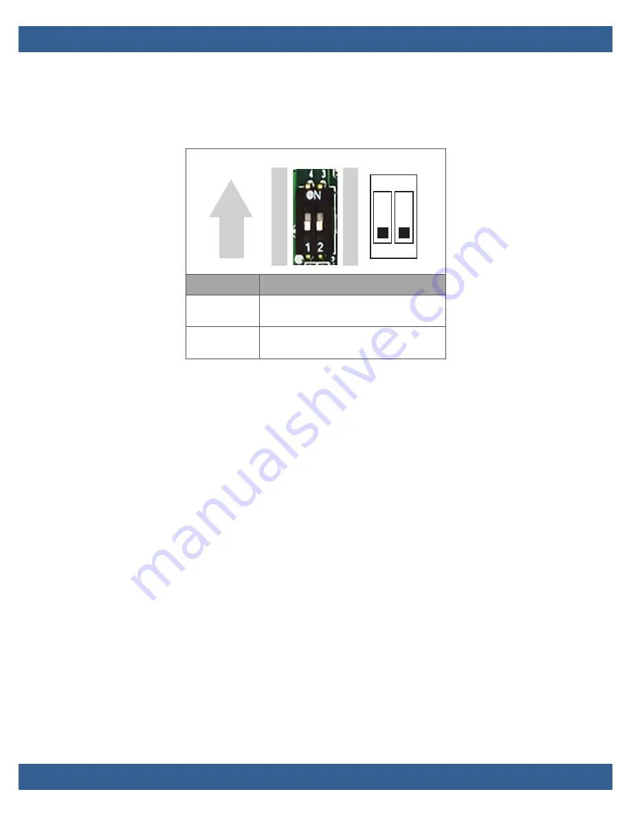
8.3.22 AT/ATX & BIOS Recovery Setup (SW2)
Select the appropriate Power On/BIOS Recovery setting using these
switches (SW2).
9.
BIOS Settings
9.1
General Information
The PPC65BP-1x includes an AMI BIOS stored in Flash ROM. Access setup
information through the BIOS setup utility to modify basic system
configuration. The configuration is stored in CMOS RAM (it is retained
during power-off). When power is applied to the system, the PPC65BP-1x
communicates with peripheral devices and checks hardware resources
against the configuration information stored in the CMOS memory. If
during startup an error is detected or the CMOS parameters need to be
initially defined, the diagnostic program prompts the user to enter the
SETUP program. Some errors are significant enough to cause the startup
to fail.
9.2
Entering Setup
To enter setup, apply power to the computer and then press the delete
key. This key (
Delete
or
Del
) must be pressed when either the splash
screen is displayed (during the system power-on self test, POST) or when
the
Press <Del> to enter SETUP
message is displayed. It may take a few
seconds before the main setup menu screen is displayed.
The following figure illustrates default setting
Switch
Description
1-4 (Port 1)
ON: AT mode
OFF:ATX mode (default)
2-3 (Port 2)
ON: Recover BIOS
OFF: Disable (default)
1
3
2
4
ON
1 2
ON
Summary of Contents for PPC65BP-1 Series
Page 59: ...PPC65BP 1x v1 0 www winsystems com Page 59 PPC65BP 12 Dimensions...
Page 60: ...PPC65BP 1x v1 0 www winsystems com Page 60 PPC65BP 15 Dimensions...
Page 61: ...PPC65BP 1x v1 0 www winsystems com Page 61 PPC65BP 17 Dimensions...
Page 62: ...PPC65BP 1x v1 0 www winsystems com Page 62 PPC65BP 19 Dimensions...


