background image


53 

Chapter 5: BIOS Setup Utility 

BIOS Setting 

Description 

Setting Option 

Effect 

Save Changes 
and Exit 

This saves the changes to the 
CMOS and exits the BIOS Setup 
program. 

<YES> 

Save changes 

Discard 
Changes and 
Exit 

This exits the BIOS Setup 
without saving the changes made 
in BIOS Setup to the CMOS. 

<YES> 

Saves the 
changes 

<NO> 

Return to the 
BIOS Setup 
Main Menu 

Save Changes 
and Reset 

Reset the system after saving the 
changes. 

<YES> 

Saves the 
changes 

<NO> 

Return to the 
BIOS Setup 
Main Menu 

Discard 
Changes and 
Reset 

Reset system setup without 
saving any changes 

<YES> 

Saves the 
changes 

<NO> 

Return to the 
BIOS Setup 
Main Menu 

Save Changes 

Save changes done so far to any 
of the setup options. 

<YES> 

Saves the 
changes 

<NO> 

Return to the 
BIOS Setup 
Main Menu 

Discard 
Changes 

Discard changes done so far to 
any of the setup options. 

<YES> 

Saves the 
changes 

<NO> 

Return to the 
BIOS Setup 
Main Menu 

Restore Default  Restore/load default values for all 

the setup options. 

<YES> 

Saves the 
changes 

<NO> 

Return to the 
BIOS Setup 
Main Menu 

Save as User 
Defaults 

Save the changes done so far as 
User defaults. 

<YES> 

Saves the 
changes 

<NO> 

Return to the 
BIOS Setup 
Main Menu 

Restore User 
Defaults 

Restore the User Defaults to all 
the setup options. 

<YES> 

Saves the 
changes 

<NO> 

Return to the 
BIOS Setup 
Main Menu 


Summary of Contents for R15IB3S-65EX

Page 1: ...this product and save this manual for future use 15 Full IP65 Stainless Class I Division 2 Intel Celeron Bay Trail M N2930 1 83 GHz Intel ATOM N2600 1 6 GHz Model no R15IB3S 65EX R15ID3S 65EX User Man...

Page 2: ......
Page 3: ...16 2 3 1 Wiring Requirements 16 2 3 2 Connecting the Interface 17 2 3 3 Workstation 18 2 3 4 Connector Pinouts 19 Chapter 3 Installation 22 3 1 Cable Mounting Considerations 23 3 2 Safety Precautions...

Page 4: ...2 15 ATEX Panel PC User Manual 6 1 Software Developer Support 56 6 2 Problem Report Form 56 Appendix 57 Appendix A Product Specifications 57 Appendix B Touchscreen 59...

Page 5: ...f the customer discovers a defect we will at his her option repair or replace the defective product at no charge to the customer provide it is returned during the warranty period of one year with tran...

Page 6: ...rrecte Safety Information WARNING AVERTISSEMENT Always completely disconnect the power cord from your chassis whenever you work with the hardware Do not make connections while the power is on Sensitiv...

Page 7: ...WARNING AVERTISSEMENT Only use the connection cords that come with the product When in doubt please contact the manufacturer Utiliser seulement les cordons d alimentation fournis avec le produit Si v...

Page 8: ...harmful interference to radio communications Operation of this equipment in a residential area is likely to cause harmful interference in which case the user will be required to correct the interferen...

Page 9: ...sment Accredited by IEC 17025 Self Declaration in accordance with EMC Directive 2004 108 EC Independent 3rd party assessment Accredited by IEC 17025 About This User Manual This User Manual provides in...

Page 10: ...er 1 Introduction This chapter gives you product overview describes features and hardware specification You will find all accessories that come with the HMI in the packing list Mechanical dimensions a...

Page 11: ...e Acetylene Hydrogen Ethylene and Propane classified areas and surface temperatures not exceeding 275 F 135 C in the US market and ATEX Gas Zone 2 Classified areas in European and other markets 1 2 Pr...

Page 12: ...elow are inside your package If any of these items are missing or damaged contact us immediately Standard factory shipment list Panel PC AC to DC adapter Power Cord USB Cable USB adapter USB Type A to...

Page 13: ...1 4 Mechanical Dimensions 1 4 1 Dimensions 15 Unit mm 1 4 2 LED Indicators LED Type Status Description Power On Power is on Off Power is off Storage Blinking Storage activity data is being read or wr...

Page 14: ...rnir un appareil de protection des survoltages a un niveau n exc dant pas 140 du voltage sp cifi au connecteur d alimentation de l appareil 2 Explosion Hazard Do not connect or disconnect the equipmen...

Page 15: ...Chapter 2 Getting Started Chapter 2 Getting Started This chapter provides information on how to connect the device to the source of power connector pinouts and the guideline to turn on off the Panel...

Page 16: ...of your device Make sure the cable fits to the connector then tighten the O ring by turning it clockwise to secure the connection 3 Connect the AC adapter to the power cord 4 Plug the power cord to a...

Page 17: ...usting the LCD Display Brightness 1 Tap the arrow on the system tray to display the hidden icons 2 Double tap the icon to display the brightness menu 3 Drag the brightness bar to adjust the brightness...

Page 18: ...gly advised that you label wiring to all devices in the system CAUTION ATTENTION Do not run signal or communication wiring and power wiring in the same conduit To avoid interference wires with differe...

Page 19: ...ed to be removed To ensure the waterproof function can work properly make sure that the protective caps and the tethers have been securely fastened whenever the connectors are not used Panel PC explod...

Page 20: ...2 The connector cables are located under the enclosure You need to connect wires first refer to Chapter 1 4 to find the connector placement install the pipe insert the wires into the pipe opening and...

Page 21: ...ith four connectors which are IP65 level and fool proofing design Use only the cables that are included in the package The pin assignments of the cables are as follows IMPORTANT Minimum input cables s...

Page 22: ...20 15 ATEX Panel PC User Manual 2 3 4 2 Ethernet LAN Cable 2 3 4 3 RS 232 Cable Optional RS 422 485...

Page 23: ...ISSEMENT Ensure that the external power source is OFF before connecting or disconnecting the DC IN jack Assurez vous que la source d alimentation externe est coup e avant de brancher et de d brancher...

Page 24: ...anel PC User Manual Chapter 3 Installation This chapter provides mounting guide for all available mounting options and hardware installation instructions Pay attention to cautions and warning to avoid...

Page 25: ...s lectriques l emplacement de la prise terre l arri re doit tre li terre locale travers un 12 AWG minimum et aussi court que possible 3 2 Safety Precautions Observe the following common safety precaut...

Page 26: ...al plate to the bottom side 2 Secure the box cover on the top side 3 Secure the box cover on the bottom side 4 M4 x 6 Secure the metal plate on the box cover to the Panel CP left and right sides 8 M5...

Page 27: ...u need to open the enclosure box cover to install VESA Plate to the enclosure of the Panel PC with customer s bracket Exploded drawing Item No Description 1 Top cover lid of the enclosure Only for IB3...

Page 28: ...e down 2 Loosen screws M4 x 6 on two metal plates that secure enclosure to the Panel PC from each side 3 Loosen the screws M3 x 6 that secure box cover on both top three screws and bottom four screws...

Page 29: ...e box cover install VESA plate to the enclosure To install VESA Plate follow the steps below Description Picture 1 Fasten four Philips M5x10 flathead screws from the inside of the box top cover 2 Secu...

Page 30: ...tion instructions Step 4 Secure the cover box on both top three screws and bottom four screws sides with M3 x 6 Philips flathead screws and fasten the screws M3 x 6 that secure box cover on the left a...

Page 31: ...tion is complete plug the power cord into a grounded AC outlet Turn on the power 3 3 1 2 Swing Arm The device can be installed on a swing arm You can purchase swing arm from RAM Mount NOTE You need to...

Page 32: ...PC User Manual Chapter 4 Maintenance This chapter provides information on regular cleaning and maintenance procedures Follow all the recommendations included in this chapter in order to ensure long p...

Page 33: ...he equipment CAUTION ATTENTION Always turn off the device and disconnect other peripherals before cleaning and maintenance procedures Toujours teindre l appareil et d brancher tous les p riph riques a...

Page 34: ...l Chapter 5 BIOS Setup Utility BIOS Setup Utility is a program for configuration basic Input Output system settings of the Panel PC for optimum use This chapter provides information on how to use BIOS...

Page 35: ...e specifications 5 2 BIOS Functions BIOS Navigation Keys BIOS navigation keys for keyboard control are listed below The following keys are enabled during POST Key Function Del Enters the BIOS setup me...

Page 36: ...language time and date BIOS Setting Description Setting Option Effect System Language Displays the system language English is set up by default Adjustment of the language Set the language in other la...

Page 37: ...options of ACPI configuration A description of the selected items will appear on the right side of the screen BIOS Setting Description Setting Option Effect ACPI Settings Configures ACPI settings Ente...

Page 38: ...ettings Enter Opens submenu Platform Trust Technology Configures Platform Trust Technology parameters Enter Opens submenu Security Configuration Configures Security parameters Enter Opens submenu 5 3...

Page 39: ...selected A description of the selected item appears on the right side of the screen For items marked with please press Enter for more options Serial Port 1 5 Use these items to set parameters related...

Page 40: ...rt Configuration You can use the screen to change GPI0 Port setting Use these items to set parameters related to PIN3 PIN14 Control 5 3 2 3 Hardware Monitor You can check PC Health Status parameters s...

Page 41: ...ou to wake up the system in a certain time Select Fixed Time to set the system to wake on the specified time Use Navigation Keys to switch among the items Day Hour Minute and Second Type the desired v...

Page 42: ...tem from S5 after dynamic time setting Select Dynamic Time to set the system to wake on the current time increase minute s 5 3 2 5 CPU Configuration Press Enter to view current CPU configuration and m...

Page 43: ...nction Intel Virtualization Technology Allows to run recent OS and applications Enabled Disabled Enable Disable this function Power Technology Control the performance and power management functions of...

Page 44: ...the OS will shut down the system 90C 87C 85C 79C 71C 63C 55C 47C 39C 31C 23C 15C Select the disable temperature for the system to shut down Passive Trip Point Specifies the temperature at which the O...

Page 45: ...Gen2 The maximum speed will be limited to 300 MB s Disabled Disables manual configuration of SATA II ports mode will be selected based on the specifications of connected drives SATA Mode This option...

Page 46: ...ATA Port 1 The option turns on or off Port 1 of SATA channels of standard IDE SATA controller chipset Enabled Disabled Turn on Enabled or turn off Disabled Port 1 SATA Port1 HotPlug This feature that...

Page 47: ...t Enable or disable this function Option ROM Messages Receiving ROM Messages Settings Force BIOS Set ROM messages parameters Network Specifies which Network option ROM is booted UEFI Only UEFI option...

Page 48: ...workaround for OSs without ECHI hand off support Disable Disables this function Enable Enables this function USB mass storage driver support User can Enable or disable USB mass storage driver support...

Page 49: ...Chapter 5 BIOS Setup Utility 5 3 2 12 Platform Trust Technology BIOS Setting Description Setting Option Effect fTPM Trusted Platform Module parameters Enabled Disabled Enables or disables this functi...

Page 50: ...nabled Disabled Enables or disables this function TXE Firmware Update TXE Firmware Update parameters Enabled Disabled Enables or disables this function TXE EOP Message TXE EOP Message parameters Enabl...

Page 51: ...r settings Enabled Disabled Enables Disables this function Restore AC Power Loss This function allows to set up booting options after a power failure Power on Power off Boot automatically after a powe...

Page 52: ...or password user password and HDD security configuration BIOS Setting Description Setting Option Effect Administrator Password Displays whether or not an administrator password has been set Enter Ente...

Page 53: ...t Boot NumLock State Enables or disables NumLock feature on the numeric keypad of the keyboard after the POST Default On On Remains On Off Remains OFF Quite Boot Determines if POST message or OEM logo...

Page 54: ...Enter Open sub menu Hard Disk Drive BBS Priorities Hard Disk Drive BBS Priorities Enter Open sub menu Network Drive BBS Priorities Network Drive BBS Priorities Enter Open sub menu 5 3 6 Save Exit The...

Page 55: ...ut saving any changes YES Saves the changes NO Return to the BIOS Setup Main Menu Save Changes Save changes done so far to any of the setup options YES Saves the changes NO Return to the BIOS Setup Ma...

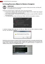
Page 56: ...the computer and when the boot screen shows up press the F6 to initiate the Recovery Wizard The following screen shows the Recovery Wizard Click Recovery button to continue A warning message about dat...

Page 57: ...IOS Setup Utility Chapter 6 Technical Support This chapter includes technical support documents and software developing kit SDK If any problem occurs fill in problem report form enclosed and immediate...

Page 58: ...________________________________________________________________ ______________________________________________________________________________ ________________________________________________________...

Page 59: ...M12 type connector for Giga LAN 1 x M12 type connector for Giga LAN COM 1 x M12 connector for RS232 422 485 Default RS232 1 x M12 connector for RS232 422 485 Default RS232 USB 1x M12 type connector f...

Page 60: ...AN Cable RJ45 female converter USB Adapter USB type A to type B Driver CD Manual VESA screws NOTE 1 Total usable memory will be less dependent upon actual system configuration 2 Length measurements do...

Page 61: ...The operational theory of a PCAP touch screen begins with two patterned Indium Tin Oxide ITO layers under a glass substrate cover which create a X axis and Y axis electric field These electric fields...

Page 62: ...Winmate Inc 9F No 111 6 Shing De Rd San Chung District New Taipei City 24158 Taiwan R O C www winmate com Copyright 2022 Winmate Inc All rights reserved...

Reviews: