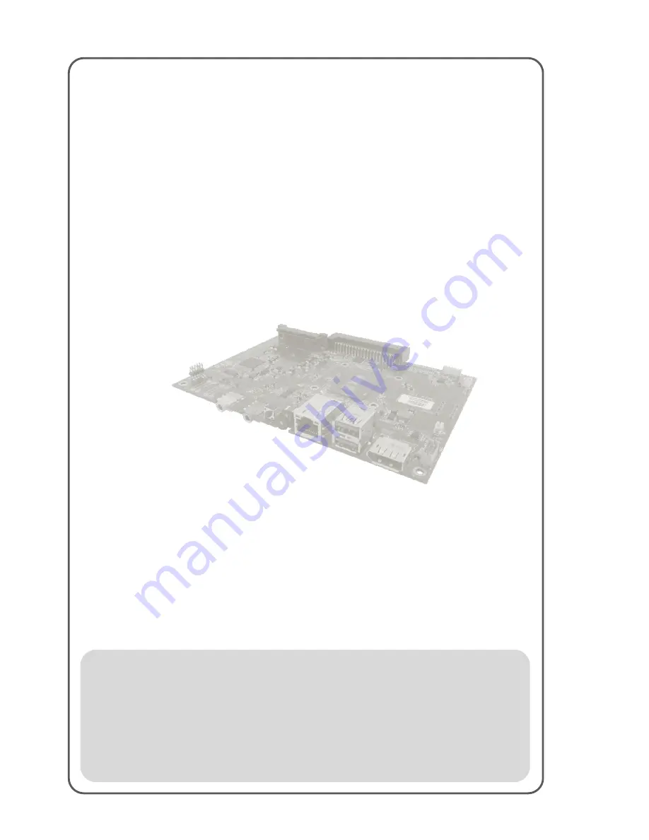
OMIW Motherboard
3.5” SBC with Intel ® 5th Generation Dual Core i5 Processors,
Display Port, LVDS, Giga Ethernet, and Mini-PCIe Interface
V110
User Manual
Version 1.0
Document Part Number:
915211171008
Page 1: ...OMIW Motherboard 3 5 SBC with Intel 5th Generation Dual Core i5 Processors Display Port LVDS Giga Ethernet and Mini PCIe Interface V110 User Manual Version 1 0 Document Part Number 915211171008 ...
Page 2: ...pecified use without further testing or modification Warranty We warrant that each of its products will be free from material and workmanship defects for a period of one year from the invoice date Standard is one year extended warranty will need to discuss with our sales representatives If the customer discovers a defect we will at its option repair or replace the defective product at no charge to...
Page 3: ...the following information before you call Product serial number Peripheral attachments Software OS version application software etc Detailed problem description The exact wording of any error messages In addition free technical support is available from our engineers every business day We are always ready to give advice on application requirements or specific information on the installation and op...
Page 4: ...and Warnings The following is an example of each type of advisory NOTE A note is used to emphasize helpful information IMPORTANT An important note indicates information that is important for you to know CAUTION A Caution alert indicates potential damage to hardware and explains how to avoid the potential problem WARNING An Electrical Shock Warning indicates the potential harm from electrical hazar...
Page 5: ... 5 Keep this equipment away from humidity 6 Put this equipment on a reliable surface during installation Dropping it or letting it fall could cause damage 7 Make sure the voltage of the power source is correct before connecting the equipment to the power outlet 8 Position the power cord so that people cannot step on it Do not place anything over the power cord 9 All cautions and warnings on the eq...
Page 6: ...OMIW Motherboard VI Revision History Version Date Note Author 1 0 12 Jul 2016 Initial release Austin Chang ...
Page 7: ...2 1 MOTHERBOARD COMPONENTS 7 2 1 1 Front Side View 7 2 1 2 Rear Side View 8 2 1 3 I O Side View 8 2 2 CONNECTOR PIN ASSIGNMENTS 9 2 2 1 Front Side 9 2 2 2 Rear Side 12 2 2 3 I O Side 17 CHAPTER 3 AMI BIOS SETUP 24 3 1 HOW AND WHEN TO USE BIOS SETUP 24 3 2 BIOS FUNCTIONS 25 3 2 1 Main Menu 25 3 2 2 Advanced Settings 27 3 2 3 Chipset Menu 44 3 2 4 Boot Menu 46 3 2 5 Security Menu 47 3 2 6 Save Exit ...
Page 8: ...MIW Motherboard VIII 4 2 GRAPHICS DRIVER 56 4 3 AUDIO DRIVER 59 4 4 ETHERNET DRIVER 61 4 5 INTEL MANAGEMENT ENGINE SOFTWARE 64 4 6 USB 3 0 DRIVER INSTALLATION WINDOWS 7 67 CHAPTER 5 TECHNICAL SUPPORT 72 ...
Page 9: ...OMIW Motherboard 1 General Information This chapter includes the OMIW motherboard background information ...
Page 10: ...rs The power supply to the OMIW together with the defined feature interfaces are being routed through the set of connectors and provide a functional system level computing solution for digital signage There is an advanced full set of I O ports including two USB3 0 one LAN port one Display Port 1 2 to connect to external display The current model allows adding Wi Fi or 3G models for better connecti...
Page 11: ...t 1 2 2 x Audio phone jack Line in Line out 1 x Power button 1 x Reset button Rear OPS Interconnector 1 x JAE 80 Pin connector OPS Standard Internal I O 1 x SIM Card Slot 1 x SATA Slot Expansion Slot 1 x Mini PCIe slot for wireless module or 3G Module Power Requirements Power Consumption 25W Burn in Test Input Voltage 12V 19V DC in via OPS interconnection Physical Characteristics Dimensions W x H ...
Page 12: ...board 3 1 3 2 Software Support The following drivers are available for the OMIW Motherboard Item Driver Windows 7 Windows 8 Windows 10 1 Chipset Driver 2 Graphics Driver 3 Audio Driver 4 Ethernet Driver 5 Intel Management Engine Software 6 USB 3 0 Driver ...
Page 13: ...User Manual Chapter 1 General Information OMIW Motherboard 4 1 4 Functional Description Function block V110 ...
Page 14: ...User Manual Chapter 1 General Information OMIW Motherboard 5 1 5 Physical Description Board Dimensions V110 ...
Page 15: ...OMIW Motherboard 6 Hardware Installation This chapter provides information on how to use jumpers and connectors on the OMIW motherboard ...
Page 16: ...ware Installation This chapter provides information on how to use jumpers and connectors on the OMIW Motherboard Be cautious while working with these modules Carefully read the content of this chapter in order to avoid any damages 2 1 Motherboard Components 2 1 1 Front Side View ...
Page 17: ...User Manual Chapter 2 Hardware Installation OMIW Motherboard 8 2 1 2 Rear Side View 2 1 3 I O Side View 2 1 3 1 Top View ...
Page 18: ... Label Function Note BT1 CMOS Battery Connector HIROSE DF13 2P 1 25H CN3 SATA Connector FOXCONN LD2722F S4GL6 CN4 DC Input 2x2pin 4 2mm ATX Connector CN5 SATA Power 2x4 wafer pitch 2 0mm CN6 VGA Connector 2x5 wafer pitch 2 0mm CN7 OPS Connector JAE TX24 80R LT H1E FAN1 System Fan Connector MOLEX 53398 0371 J1 EDP Output Connector 2x10 Wafer pitch 1 0mm BT1 CMOS Battery Connector Pin Signal Name 1 ...
Page 19: ...Name Pin Signal Name 1 GND 2 TXP 3 TXN 4 GND 5 RXN 6 RXP 7 GND 8 3 3V 9 3 3V 10 3 3V 11 GND 12 GND 13 GND 14 5V 15 5V 16 5V 17 GND 18 NC 19 GND 20 NC 21 NC 22 NC CN4 DC Input CN5 SATA Power Pin Name Pin Name 1 GND 2 GND 3 VCC 4 VCC Pin Name Pin Name 1 12V 2 12V 3 GND 4 GND 5 GND 6 GND 7 5V 8 5V ...
Page 20: ...therboard 11 CN6 VGA Connector FAN1 System Fan Connector BT1 Backup Battery Pin Name Pin Name 1 DDC_DATA 2 5V 3 DDC_CLOCK 4 RED 5 Horizontal Sync 6 GREEN 7 Vertical Sync 8 BULE 9 GND 10 GND Pin Signal Name 1 GND 2 Fan Power 3 Sense Pin Name 1 GND 2 BAT ...
Page 21: ...Mini PCIE Slot FOXCONN AS0B226 S40N 7F DIMM1 DDR3 Slot FOXCONN AS0A626 N2SN 7H CN10 SIM Card Connector CN10 Micro SIM Card Connector CN11 Mini PCIE Slot Pin Signal Name Pin Signal Name 1 PCIE_WAKE 2 3 3V 3 NC 4 GND Pin Name C1 VREG_USIM C2 USIM_RST C3 USIM_CLK C5 GND C6 USIM_VPP C7 USIM_DAT SW USIM_DET Default High Active Low G1 NC G2 NC G3 GND G4 GND ...
Page 22: ...ESET 15 GND 16 VPP 17 NC 18 GND 19 NC 20 3G RFON 21 GND 22 PLTRST 23 PCIE_RXN2 24 3 3Vaux 25 PCIE_RXP2 26 GND 27 GND 28 1 5V 29 GND 30 SMB_CLK 31 PCIE_TXN2 32 SMB_DATA 33 PCIE_TXP2 34 GND 35 GND 36 USB_PN2 37 GND 38 USB_PP2 39 3 3Vaux 40 GND 41 3 3Vaux 42 NC 43 GND 44 NC 45 NC 46 NC 47 NC 48 1 5V 49 NC 50 GND 51 NC 52 3 3V DIMM1 DDR3 Slot ...
Page 23: ...DQ7 19 GND 20 GND 21 DQ8 22 DQ12 23 DQ9 24 DQ13 25 GND 26 GND 27 DQS_DN1 28 DM1 29 DQS_DP1 30 DDR3_DRAMRST 31 GND 32 GND 33 DQ10 34 DQ14 35 DQ11 36 DQ15 37 GND 38 GND 39 DQ16 40 DQ20 41 DQ17 42 DQ21 43 GND 44 GND 45 DQS_DN2 46 DM2 47 DQS_DP2 48 GND 49 GND 50 DQ22 51 DQ18 52 DQ23 53 DQ19 54 GND 55 GND 56 DQ28 57 DQ24 58 DQ29 59 DQ25 60 GND 61 GND 62 DQS_DN3 63 DM3 64 DQS_DP3 65 GND 66 GND 67 DQ26 6...
Page 24: ...94 1 5V 95 MA3 96 MA2 97 MA1 98 MA0 99 1 5V 100 1 5V 101 CK_DP2 102 CK_DP3 103 CK_DN2 104 CK_DN3 105 1 5V 106 1 5V 107 MA10 108 BS1 109 BS0 110 RAS_N 111 1 5V 112 1 5V 113 WE_N 114 CS_N2 115 CAS_N 116 ODT2 117 1 5V 118 1 5V 119 MA13 120 ODT3 121 CS_N3 122 NC 123 1 5V 124 1 5V 125 NC 126 VREF_CA 127 GND 128 GND 129 DQ32 130 DQ36 131 DQ33 132 DQ37 133 GND 134 GND 135 DQS_DN4 136 DM4 137 DQS_DP4 138 ...
Page 25: ... DQ47 161 GND 162 GND 163 DQ48 164 DQ52 165 DQ49 166 DQ53 167 GND 168 GND 169 DQS_DN6 170 DM6 171 DQS_DP6 172 GND 173 GND 174 DQ54 175 DQ50 176 DQ55 177 DQ51 178 GND 179 GND 180 DQ60 181 DQ56 182 DQ61 183 DQ57 184 GND 185 GND 186 DQS_DN7 187 DM7 188 DQS_DP7 189 GND 190 GND 191 DQ58 192 DQ62 193 DQ59 194 DQ63 195 GND 196 GND 197 SA0_DIM0 198 PM_EXTTS0_N 199 3 3V 200 SMB_DATA 201 SA1_DIM0 202 SMB_CL...
Page 26: ...AN1 Ethernet connector UDE RT7 174AAM1A USB3 0 USB 3 0 USB Type A SW1 Power Key TC003 N11AABUBXX RK WITH LED SW2 Reset Key TSVB 31L 3mm 90 J1 eDP Output connector CN1 Display Port CN8 Audio Line out Green Pin Symbol Pin Symbol 1 Lane 0 2 GND 3 Lane 0 4 Lane 1 5 GND 6 Lane 1 7 Lane 2 8 GND 9 Lane 2 10 Lane 3 11 GND 12 Lane 3 13 AUX_EN 14 GND 15 AUX 16 GND 17 AUX 18 Hot Plug 19 GND 20 DP_PWR Pin Sig...
Page 27: ... In_R 3 AGND 4 Line In_DET 5 AGND 6 AGND Pin Signal Name 1 Tranceice Data 2 Tranceice Data 3 Receive Data 4 Bi directional Data 5 Bi directional Data 6 Receive Data 7 Bi directional Data 8 Bi directional Data Pin Name Pin Name 1 5V 2 USB_D 3 USB_D 4 GND 5 STDA_SSRX 6 STDA_SSRX 7 GND_DRAIN 8 STDA_SSTX 9 STDA_SSTX 10 5V 11 USB_D 12 USB_D 13 GND 14 STDA_SSRX 15 STDA_SSRX 16 GND 17 STDA_SSTX 18 STDA_S...
Page 28: ...User Manual Chapter 2 Hardware Installation OMIW Motherboard 19 SW2 Reset Key 1 GND 2 GND 3 CPUPWRON 4 CPUPWRON 5 GND 6 V3 3S Pin Name 1 PM_SYSRST 2 GND 3 GND 4 GND ...
Page 29: ...Motherboard 20 J1 eDP Output Connector Pin Name Pin Name 1 TXP0_C 2 VDD_eDP 3 TXN0_C 4 VDD_eDP 5 GND 6 VCC_EDP_BKLT 7 TXP1_C 8 VCC_EDP_BKLT 9 TXN1_C 10 VCC_EDP_BKLT 11 GND 12 EDP_HPD 13 AUXP 14 GND 15 AUXN 16 GND 17 BKLT_EN 18 GND 19 BKLT_CTRL 20 GND ...
Page 30: ...OMIW Motherboard 21 AMI BIOS Setup This chapter contains BIOS Configuration and OS Recovery information for OMIW motherboard ...
Page 31: ...1 DDP_3N 2 DDP_3P 3 GND 4 DDP_2N 5 DDP_2P 6 GND 7 DDP_1N 8 DDP_1P 9 GND 10 DDP_0N 11 DDP_0P 12 GND 13 DDP_AUXN 14 DDP_AUXP 15 DDP_HPD 16 GND 17 TMDS_CLK 18 TMDS_CLK 19 GND 20 TMDS0 21 TMDS0 22 GND 23 TMDS1 24 TMDS1 25 GND 26 TMDS2 27 TMDS2 28 GND 29 H_DAT_OUT 30 H_CLK_OUT 31 HP_DET_OUT 32 GND 33 DC_IN 34 DC_IN 35 DC_IN 36 DC_IN 37 DC_IN 38 DC_IN 39 DC_IN 40 DC_IN 41 RSVD 42 RSVD 43 RSVD 44 RSVD ...
Page 32: ...60 USB_PN2 61 USB_PP2 62 GND 63 USB_PN1 64 USB_PP1 65 GND 66 USB_PN0 67 USB_PP0 68 GND 69 REAR_L 70 REAR_R 71 HDMI_CEC_OUT 72 PB_DET 73 PS_ON 74 PWR_STATUS 75 GND 76 GND 77 GND 78 GND 79 GND 80 GND CN3 SATA HDD Pin Name Pin Name 1 GND 2 SATA_TXP0 3 SATA_TXN0 4 GND 5 SATA_RXN0 6 SATA_RXP0 7 GND 8 SATA_3V3 9 SATA_3V3 10 SATA_3V3 11 GND 12 GND 13 GND 14 V5S 15 V5S 16 V5S 17 GND 18 NC 19 GND 20 NC 21 ...
Page 33: ...tory default settings 3 Modifying the specific hardware specifications 4 Necessity to optimize specifications BIOS Navigation Keys The following keys are enabled during POST Key Function Del Enters the BIOS setup menu F7 Display the boot menu Lists all bootable devices that are connected to the system With cursor and cursor and by pressing ENTER select the device used for the boot Pause Pressing t...
Page 34: ...d settings or to activate certain system features The follwoing sections describe the configuration options found in the menu items 3 2 1 Main Menu The Main menu displays the basic information about yoursystem including BIOS version processor RC version system language time and date When you enter BIOS setup the first menu that appears on the screen is the main menu It contains the system informat...
Page 35: ...guage Set the language in other language The language in this device is English System Date Time This is current date setting The time is maintained by the battery when the device is turned off Date and time changes Set the date in the format mm dd yyyy The time in the format hh mm ss Access Level The current user access settings Changes to the level of access Administrator is set up by the defaul...
Page 36: ...elect any of the items on the left frame of the screen to go to the sub menu for the item such as CPU Configuration You can use the Arrow keys enter all advanced BIOS setup options The advanced BIOS setup menu is shown below The submenus described on the following pages CAUTION Handle advanced BIOS settings page with caution Any changes can affect the operation of your computer ...
Page 37: ...iguration Configures Super I O settings Enter Opens submenu Hardware Monitor Configures H W Monitor settings Enter Opens submenu S5 RTC Wake Settings Configures RTC Wake parameters Enter Opens submenu SATA Configuration Configures SATA parameters Enter Opens submenu CSM Configuration Configures CSM parameters Enter Opens submenu USB Configuration Configures USB parameters Enter Opens submenu Intel...
Page 38: ...User Manual Chapter 3 AMI BIOS Setup OMIW Motherboard 29 3 2 2 1 CPU Configuration CPU Configuration allows you to change CPU settings Use key arrows to navigate through the menu ...
Page 39: ...ead per enabled core is enabled Execute Disable Bit Allows the processor to classify areas in memory where application code can or cannot execute and reduce system exposure to viruses and malicious code Enabled Prevents certain classes of malisious baffer overflow attacks when combined with a supporting OS Disabled Disable this function Intel Virtualization Technology Help accelerate virtual machi...
Page 40: ...run faster than the frequency recommendedby the manufacturer Enabled Disabled Enables or disables this function CPU C States C States architecture can further reduce power consumption from the basic C1 Halt State statethat blocks clock cycles to the CPU Enabled Disabled Enables or disables this function CPU DTS Determine which temperature values are used by ACPI terminal management Disabled ACPI t...
Page 41: ... security device Enabled Disabled Set required configuration TPM State Enable or disable TPM state Enabled Disabled Set required configuration Pending Operation Control the Security Device None TPM Clear Schedule an Operation for the Security Device Device Select Select devices will be enumerated Auto TPM 1 2 TPM 2 0 TPM 1 2 will restrict support to TPM 1 2 devices TPM 2 0 will restrict ...
Page 42: ...nual Chapter 3 AMI BIOS Setup OMIW Motherboard 33 3 2 2 3 ACPI Settings support to TPM 2 0 devices Auto will support both with the default set to TPM 2 0 devices if not found TPM 1 2 devices will be enumerated ...
Page 43: ...inguished monitor All other components processor memory chipset operate in normal mode only a transition to a low frequency S3 Suspended to RAM Before going into S3 all the information about the state of the various components is stored in the memory Lock Legacy Resources Prevents the OS from changing resources to serial parallel or diskette controller Enabled Disabled Enables or disables this fun...
Page 44: ...ameters User can Enable Disable the serial port and select optimal settings for the Super IO Device Enable Disable Default Enable Enable or Disable Serial Port COM Super IO Watch Dog Timer Setting The watchdog timer circuit has to be triggered within a specified time by the application software If the watchdog is not triggered because proper software execution fails or a hardware malfunction occur...
Page 45: ...2 4 1 Serial port Configuration BIOS Setting Description Setting Option Effect Serial Port Select Serial Port RS232 RS422 RS485 Rx RS485 Tx Choose Serial Port Settings Change Settings Allow Change Serial Port Settings AUTO UART Mode Show which serial port is used ...
Page 46: ...User Manual Chapter 3 AMI BIOS Setup OMIW Motherboard 37 3 2 5 5 Hardware Monitor Hardware Monitor shows PC health status information ...
Page 47: ...scription Setting Option Effect Wake System from S5 Enables or disables system wake on alarm event It allows you to wake up the system in a certain time Disabled Disable this function Fixed Time System will awake at the hr min sec specified Dynamic Time System will awake at current time increase min s ...
Page 48: ...llows users to enable or disable the SATA controller s Enabled Disabled Enables or disables this function SATA Mode Selection Allows users to select mode of SATA controller s Enabled Disabled Enables or disables this function SATA Controller Speed Allows users to select mode of SATA Controller Speed Enabled Disabled Enables or disables this function ...
Page 49: ...bility Support Module Provides legacy BIOS compatibility by emulating a BIOS environment allowing legacy operating systems and some option ROMs that do not support UEFI to still be used Enabled Disabled Enables or disables this function GateA20 Active Allows to control the inclusion way of the address of bus A20 Upon Request Set the required parameters ...
Page 50: ... to control Boot Option Filter settings Legacy Only Enable Legacy Boot Mode UEFI Enables UEFI Boot Mode Network Allows to control Network boot settings Legacy Enable Legacy Boot Mode UEFI Enables UEFI Boot Mode Storage Allows to control Storage boot settings Legacy Enable Legacy Boot Mode UEFI Enables UEFI Boot Mode Video Allows to control Video boot settings Legacy Enable Legacy Boot Mode UEFI En...
Page 51: ...is a workaround for OSs without XHCI hand off support Disabled Disables this function Enabled Enables this function EHCI Hand off This is a workaround for OSs without ECHI hand off support Disabled Disables this function Enabled Enables this function USB Mass Storage Driver Support User can Enable or disable USB mass storage driver support Disabled Disables this function Enabled Enables this funct...
Page 52: ...er up delay Maximum time the device will take before it properly reports itself to the host controller Auto Uses default value for a root port it is 100 ms for a Hub port the delay is taken from Hub descriptor Mass Storage Device Mass storage device emulation type AUTO enumerates devices less than 530MB as floppies Forced FDD option can be used to force HDD formatted drive to boot as FDD Configure...
Page 53: ...OMIW Motherboard 44 3 2 3 Chipset Menu BIOS Setting Description Setting Option Effect System Agent SA Configuration Configures System Agent SA settings Enter Opens submenu PCH IO Configuration Congigures PCH IO settings Enter Opens submenu ...
Page 54: ...iption Setting Option Effect VT d Intel Virtualization Technology for Directed I O Provides hardware mechanisms for building a virtualized environment with complete application to I O device data transfer isolation Enabled Enable this function Graphics Configuration Configures graphics settings Enter Opens submenu ...
Page 55: ...boot device from which to load the operating system BIOS Setting Description Setting Option Effect Setup Prompt Timeout Allows user to configure the number of seconds to stay in BIOS setup prompt screen Enter Set the prompt timeout Boot NumLock State Enables or disables NumLock feature on the numeric keypad of the keyboard after the POST Default On On Remains On Off Remains OFF Quite Boot Determin...
Page 56: ...Ex Boot Option 1 hard drive Hard drive as the first priority 3 2 5 Security Menu This section allows to configure and improve system and set up some system features according to your preferences BIOS Setting Description Setting Option Effect Administrator Password Displays whether or not an administrator password has been set Enter Enter password User Password Display whether or not a user Passwor...
Page 57: ...ave changes Discard Changes and Exi This exits the BIOS Setup without saving the changes made in BIOS Setup to the CMOS Enter YES Saves the changes Enter NO Return to the BIOS Setup Main Menu Save Changes and Reset Reset the system after saving the changes Enter YES Saves the changes Enter NO Return to the BIOS Setup Main Menu Discard Changes and Reset system setup without saving any changes Enter...
Page 58: ...p Main Menu Restore Default Restore load default values for all the setup options Enter YES Saves the changes Enter NO Return to the BIOS Setup Main Menu Save as User Defaults Save the changes done so far as User defaults Enter YES Saves the changes Enter NO Return to the BIOS Setup Main Menu Restore User Defaults Restore the User Defaults to all the setup options Enter YES Saves the changes Enter...
Page 59: ... series PC IMPORTANT Before starting the recovery process be sure to backup all user data as all data will be lost after the recovery process Follow the procedure below to enable quick one key recovery procedure Plug in the AC adapter to OMIW computer Make sure the computer stays plugged in to power source during the recovery process Turn on the computer and when the boot screen shows up press the...
Page 60: ... show up Make sure the data is backed up before recovery and click Yes to continue Wait the recovery process to complete During the recovery process a command prompt will show up to indicate the percent of recovery process complete The computer will restart automatically after recovery completed ...
Page 61: ...OMIW Motherboard 52 Driver Installation This chapter describes how to install all necessary drivers ...
Page 62: ...vers 4 1 Chipset Driver The Intel Chipset Drivers should be installed first before the software drivers enable Plug Play INF support for Intel chipset components Follow the instructions below to complete the installation Step 1 Insert the CD that comes with the motherboard Open the file document Chipset Driver and click Setup exe to install driver ...
Page 63: ...User Manual Chapter 4 Driver Installation OMIW Motherboard 54 Step 2 Click Next to start the installation Step 3 Click Next to continue the installation ...
Page 64: ...User Manual Chapter 4 Driver Installation OMIW Motherboard 55 Step 4 Click Yes I want to restart this computer now to finish installation ...
Page 65: ...c driver to enable the function Intel Graphic supports versatile display options and 32 bit 3D graphics engine Triple independent display enhanced display modes for widescreen flat panels for extend twin and clone display mode Step 1 Insert the driver CD into your system s CD ROM drive You can see the driver folders items Navigate to the Graphic Driver folder and click setup exe to complete the in...
Page 66: ...User Manual Chapter 4 Driver Installation OMIW Motherboard 57 Step 2 Click Next to install the driver Step 3 Click Yes to agree with the license terms ...
Page 67: ...User Manual Chapter 4 Driver Installation OMIW Motherboard 58 Step 4 Click Next to install the driver Step 5 Click Yes I want to restart this computer now to finish installation ...
Page 68: ...s integrates two stereo ADCs that can support a stereo microphone and feature Acoustic Echo Cancellation AEC Beam Forming BF and Noise Suppression NS technology The user must confirm which operating system is running on the OMIW Motherboard before installing the Audio drivers Follow the steps below to complete the installation of the Realtek ALC886 Audio drivers You will quickly complete the insta...
Page 69: ...User Manual Chapter 4 Driver Installation OMIW Motherboard 60 Step 2 Click Next to start the installation Step 3 Click Yes I want to restart my computer now to finish the installation ...
Page 70: ...operating system is used on the OMIW Motherboard before installing the Ethernet drivers Follow the steps below to complete the installation of the Intel I210IT Gigabit LAN Controller I218LM Gigabit LAN drivers You will quickly complete the installation Step 1 Insert the driver CD and select the LAN Driver folder ...
Page 71: ...User Manual Chapter 4 Driver Installation OMIW Motherboard 62 Step 2 Extract the PROWinX64_19 0 file and click Next to install the driver Step3 Click Next to agree with the license terms ...
Page 72: ...User Manual Chapter 4 Driver Installation OMIW Motherboard 63 Step 4 Click Next to install the driver Step 5 Click Finish to complete the driver installation ...
Page 73: ...e Software This installation program installs the Intel ME software components required for the platform on which you are installing and installs only those components that match your platform s capabilities Step 1 Insert the driver CD and select the Intel ME 9 0 folder and click Setup exe ...
Page 74: ...User Manual Chapter 4 Driver Installation OMIW Motherboard 65 Step 2 Click Next to continue the installation Step 3 Click Yes to agree with the License terms ...
Page 75: ...ser Manual Chapter 4 Driver Installation OMIW Motherboard 66 Step 4 Choose I accept the terms of the license agreement and click Next to continue Step 5 Click Finish to complete the software installation ...
Page 76: ... system of the device is Windows Embedded 8 1 Industry or Windows Embedded 8 Standard users can skip this installation Step 1 Locate the hard drive directory where the driver files are stored with the browser or the explore feature of Windows Step 2 Double click the Setup exe from this directory Step 3 Click Next to continue ...
Page 77: ...iver Installation OMIW Motherboard 68 Step 4 Read the License Agreement and click Yes to proceed Step 5 Review Readme File Information and click Next to proceed Step 6 When the Setup Progress is complete click Next to proceed ...
Page 78: ...User Manual Chapter 4 Driver Installation OMIW Motherboard 69 ...
Page 79: ...User Manual Chapter 4 Driver Installation OMIW Motherboard 70 Step 7 Click Yes I want to restart this computer now to finish and then restart your computer ...
Page 80: ...OMIW Motherboard 71 Technical Support This chapter contains directory to technical support ...
Page 81: ... available from our engineers every business day We are always ready to give advice on application requirements or specific information on the installation and operation of any of our products If any problem occurs fill in problem report form enclosed and immediately contact us To find Drivers and SDK please refer to the Driver CD that comes in the package or contact us ...