


•
Venting/sealing unit
The venting/sealing unit supplies compressed air into the exhaust gas pipes for the functions
that follow:
○
Blow out the exhaust gas from the reactor and the pipes after stop of the HP SCR
system
○
Seal the reactor during HP SCR bypass operation.
•
Soot blowing unit
The soot blowing unit removes soot deposits at regular intervals from the catalyst elements
in the reactor.
•
Valves
The valves in the HP SCR system are used for the different operation modes. The HP SCR
system has the valves that follow. In parenthesis you find the position of the valves, if there
is a complete stop of the current supply (fail position):
○
V1 - Reactor inlet valve (FO - fail open)
○
V2 - Reactor outlet valve (FO - fail open)
○
V3 - Reactor bypass valve (FO - fail open)
○
V4 - Turbine bypass valve (FC - fail closed)
○
V7 - Reactor relief valve (FO - fail open).
NOTE:
In the fail condition, the engine operates in Tier II mode.
The turbine bypass valve (V4) is also used for other functions of the ECS, E.g. for low-load
tuning (LLT) or for steam production control (SPC).
For more data about the function of the valves, refer to the chapters that follow.
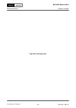
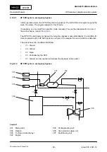
Fig 4-9
HP SCR system - layout
V1
V2
V3
V7
V4
003
001
007
006
005
004
002
X72-B
AA00-9270-00AAA-043A-A
Operation Manual
HP Selective catalytic reduction system
Winterthur Gas & Diesel Ltd.
- 97 -
Issue 003 2021-12


