OCEAN S7
Montage- und Bedienungsanleitung
DE
Installation and operating instructions
EN
Page 1: ...OCEAN S7 Montage und Bedienungsanleitung DE Installation and operating instructions EN Montage und Bedienungsanleitung DE Installation and operating instructions EN ...
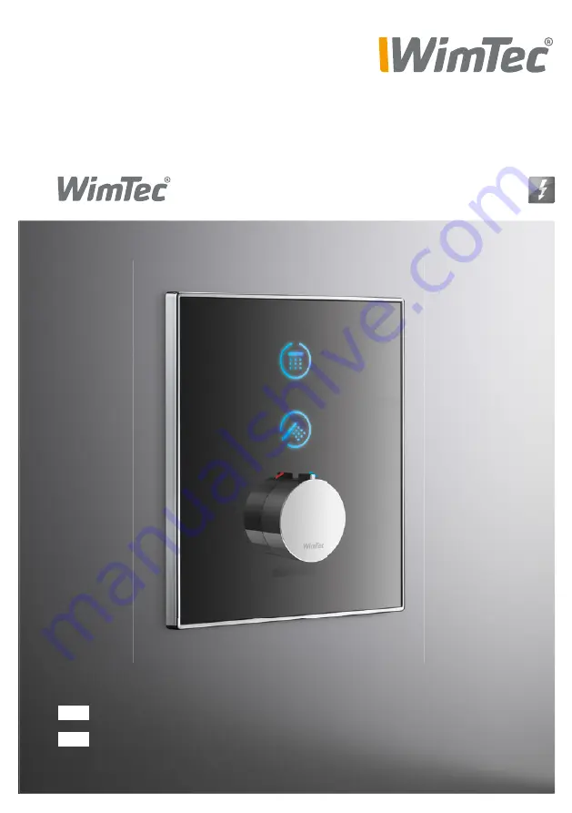
Page 2: ...olgende Produkte Glas weiß Glas schwarz WimTec OCEAN S7 12 V 119 008 119 015 WimTec OCEAN S7 TD 12 V 118 902 118 919 Lieferumfang Sicherheitsglas Frontplatte Montagerahmen mit integrierter Elektronik Thermostatgriff mit Heißwassersperre und Befesti gungsmaterial ohne UP Netzteil Wichtige Installationshinweise UP Dose für optionales Netzteil außerhalb des Schutzbereichs vor sehen Die Montage und In...
Page 3: ...nstellregler 7 DIP Schalter 7 Rohbauset 8 Montage 9 Thermische Desinfektion 13 Bedienung 14 Einschalten 14 Ausschalten 14 Reinigungsstopp 15 Funktionseinstellung 16 Verbrühschutz 16 Abschalt Automatik 17 Warmlauf 18 Intelligente Freispül Automatik 19 Spülstoppzeit 20 Nachlaufzeit 20 Ersatzteile Rohbauset 21 Ersatzteile Duscharmatur 22 ...
Page 4: ...omatik aktivierbar Spülintervall nach 3 h bis 48 h Nichtbenutzung Spüldauer 10 s oder 20 s Reinigungsstopp aktivierbar für 5 min Fließdruck 0 05 bis 0 6 MPa 0 5 bis 6 bar Statischer Druck max 0 8 MPa 8 bar Thermostat mit Heißwassersperre 38 C Wassertemperatur max 70 C max 80 C für max 10 min Durchflussmenge max 22 l min bei 0 3 MPa 3 bar Durchflussmenge Handbrause max 21 l min bei 0 3 MPa 3 bar Wa...
Page 5: ...IG R 1 2 IG Abgang Regendusche 169 140 152 min 95 max 120 Mauerwerk 23 26 Fliese Putz Dicht manschette Spannungsversorgung 2 x 0 5 mm2 max 100 m Gesamt Kabellänge Achtung Netzteil nicht im Rohbauset oder eventuellen Schutzbereichen anbringen Steuerleitung für Variante mit TD 2 x 0 5 mm2 max 100 m Gesamt Kabellänge keine Sternverkabelung Alle Maße in mm Rohbauset S7 ...
Page 6: ...en Regler H Dip Schalter zum Einstellen der Funktionen I Anschluss Bypass Magnet ventil f therm Desinfektion J Anschluss MV Handbrause K Anschluss MV Kopfbrause L Anschluss Erdung M Anschlussklemmen für 12 V Spannungsversorgung N Anschluss Ansteuerung für thermische Desinfektion O Anschluss Glasplatte P Anschluss Infrarot Sensor Einstellelemente am Elektronikmodul Frontplatte C 1 2 3 4 5 6 ON OFF ...
Page 7: ... min voreingestellt 10 s bis 20 min einstellbar G Reichweiten Regler für den Ansprechbereich 70 cm voreingestellt 30 cm bis 70 cm einstellbar Einstellregler DIP Schalter Funktion Beschreibung 1 Verbrühschutz 1 Seite 16 2 Abschalt Automatik Seite 17 3 Warmlauf 1 Seite 18 4 Intelligente Freispül Automatik Seite 19 5 Freispül Dauer ON 20 s OFF 1 10 s Seite 20 6 Nachlaufzeit ON 5 s OFF 1 2 s Seite 20 ...
Page 8: ...t 1 Magnetventil für Kopfbrause 2 Magnetventil für Handbrause 3 Magnetventil für thermische Desinfektion nur bei Art Nr 118 993 4 Absperrventil bei Auslieferung geschlossen 5 Schmutzsieb und Rückflussverhinderer 6 Thermostat 12 V PWH PWC 1 2 3 4 4 5 5 6 ...
Page 9: ... 3 Ggf zwischen Wand und Rohbauset mit Silikon abdichten 4 Wasserzuleitung absperren 5 Beide Vorabsperrungen mit einem Schraubendreher öffnen 6 Adapter für Thermostat mit Inbus 2 5 montieren ACHTUNG Folgende Schritte unbe dingt in beschriebener Reihenfolge ausführen Die Montage Fotos sind laut WimTec OCEAN mit thermischer Desinfektion 1 3 4 6 ...
Page 10: ...e Markierung Kopfbrause rot therm Desinfektion 9 Elektro Anschluss am Elektronikmodul herstellen Auf Pol ung achten und Erdungsdraht an der Wasserstecke befestigen 10 Ggf Steuerleitung für thermische Desinfektion 2 x 0 5 mm2 einziehen und am Elektronikmodul anschließen siehe Seite 13 11 Gewünschte Funktions Einstellungen am Elektronikmodul vornehmen siehe Seite 7 12 Elektronikmodul in das Rohbause...
Page 11: ...en der Schrauben darauf achten dass sich der Montagerahmen nicht verformt Beigelegtes Spezi alfett an der Dichtung vorne auftragen 15 Montagerahmen mit Infrarot Sensorik an der Elektronik anschließen 16 Glas Frontplatte an die Elektronik anschließen 17 Mischerposition kontrollieren weißer Punkt zeigt nach oben 18 Position des Mischergriffs kontrollieren Absperrknopf zeigt senkrecht nach oben ACHTU...
Page 12: ...abei beginnt das Leuchtsymbol langsam zu pulsieren Sollten es die räum lichen Gegebenheiten nicht ermöglichen dass sich jemand im Ansprechbereich befindet so ist ein Objekt z B Hand während des gesamten Funktionstests permanent ca 10 bis 15 cm vor dem Infrarot Raumüberwachungs sensor unmittelbar unterhalb der Temperatureinstellung zu halten Andernfalls kann es dazu führen dass sich die Dusche nich...
Page 13: ... aktivier tem Verbrühschutz Dip 1 On siehe Seite 16 sofort vorzeitig abgebrochen falls sich ein Benutzer in den Ansprechbereich siehe Seite 7 begibt In diesem Fall beginnt die thermische Desinfektion erneut wenn sich 2 Minuten kein Benutzer im Ansprechbereich aufgehalten hat Es muss für eine ausreichende Entlüftung gesorgt werden damit der Verbrühschutz zuverlässig funktioniert Näheres siehe Seite...
Page 14: ...endusche Handbrause AquaCap Sensortaste Durch erneutes Antippen der aktivierten Wasserabga bestelle wird der Wasserfluss beendet Regendusche Handbrause Sicherheitsspülstopp Nach Ablauf der eingestellten Spülstoppzeit siehe Seite 7 schaltet die Dusche ab Abschalt Automatik DIP 2 ON siehe Seite 7 Nach dem Verlassen des Ansprechbereichs schaltet die Dusche automatisch ab 3 Wasserabgabestelle wechseln...
Page 15: ...n blinken 3mal und der Reinigungsstopp ist für 5 min aktiviert Während des Reinigungs stopps blinken die beiden AquaCap Sensortasten abwechselnd Reinigungsstopp deaktivieren automatisch Die Armatur geht nach 5 min automatisch wieder in den Normalbetrieb über Reinigungsstopp deaktivieren manuell Zum vorzeitigen Beenden den Magnetstift erneut an den Raum zwischen den beiden AquaCap Sensortas ten füh...
Page 16: ... Desinfektion siehe Seite 13 Eine starke Dampfentwicklung vor der Duscharmatur kann zu einem unbeabsichtigen Abbruch der thermischen Desinfektion führen Für diesen Fall sollte die Verbrühschutz Funktion deaktiviert werden DIP Schalter 1 ON Verbrühschutz aktiviert voreingestellt DIP Schalter 1 OFF Verbrühschutz deaktiviert Diese Sicherheits Funktion sollte nach Möglichkeit immer aktiviert bleiben 3...
Page 17: ...erlässt i Tipp Wenn der Benutzer bei aktivierter Abschalt Automatik unabsichtlich den Ansprechbereich beim Duschen verlässt wird empfohlen die verlängerte Nachlaufzeit von 5 s zu aktivieren DIP 6 ON Dient zum automatischen Stoppen des Wasserflusses sobald der Benutzer den Ansprechbereich der Duscharmatur verlässt DIP Schalter 2 ON Abschalt Automatik aktiviert DIP Schalter 2 OFF Abschalt Automatik ...
Page 18: ...ür 30 s ohne dass sich der Benutzer im Ansprechbereich befinden muss und schaltet danach automatisch ab Tritt während dieser 30 s der Benutzer für mindestens 5 s in den Ansprechbereich geht die Dusche wieder in den Normalbetrieb über ON OFF 2 3 4 5 6 1 Warmlauf DIP Schalter 3 Dient zum Freispülen der Warmwasserleitung ohne dass der Benutzer vor der Dusche im Ansprechbereich verweilen muss nur bei ...
Page 19: ...ter 4 OFF Freispül Automatik deaktiviert voreingestellt Zeitintervall Einstellbar am Intervall Regler von 3 48 h siehe Seite 7 Freispül Automatik Wird die Armatur für die ein gestellte Zeit nicht benutzt löst die Armatur eine auto matische Freispülung der Regendusche für 10 s oder 20 s siehe Seite 7 aus Sicherheit Befindet sich ein Benutzer im Ansprechbereich oder ist der Reinigungsstopp aktiviert...
Page 20: ...P Schalter 6 ON Nachlaufzeit beträgt 5 s DIP Schalter 6 OFF Nachlaufzeit beträgt 2 s voreingestellt ON OFF 2 3 4 5 6 1 Nachlaufzeit DIP Schalter 6 ON OFF 2 3 4 5 6 1 Legt die Laufzeit der automatischen Freispülung fest DIP Schalter 5 ON Laufzeit der automatischen Freispülung beträgt 20 s DIP Schalter 5 OFF Laufzeit der automatischen Freispülung beträgt 10 s voreingestellt ...
Page 21: ...ter 1 Stk Rückflussverhinderer 1 Stk Filterabdeckung Absperrung 1 Stk Thermostat komplett Adapter für Thermostat Verlängerungsset f Thermostat 231 205 119 770 119 787 119 794 119 763 120 530 120 547 120 790 Bezeichnung Art Nr Art Nr 231 205 119 770 119 794 119 763 120 530 120 547 120 790 119 787 ...
Page 22: ...ik Modul für thermische Desinfektion inkl Montagerahmen Glas Frontplatte weiß chrom Glas Frontplatte schwarz chrom Magnetstift Thermostatgriff Sicherungsschraube Netzteil 1 fach Netzteil 5 fach 124 460 124 453 120 639 120 622 124 385 115 536 113 877 117 899 113 792 Bezeichnung Art Nr Art Nr 124 460 124 453 115 536 113 877 117 899 113 792 120 639 120 622 124 385 ...
Page 23: ......
Page 24: ...schwarz WimTec OCEAN S7 12 V 119 008 119 015 WimTec OCEAN S7 TD 12 V 118 902 118 919 Delivery scope Safety glass front plate mounting frame with integrated electro nics thermostat knob with hot water barrier mounting material without power supply Important installation notes Mounting and installation may only be performed by a qualified service provider in accordance with DIN 1988 ÖVE ÖNORM E8001 ...
Page 25: ...s 29 DIP switches 29 Flush mount set 30 Assembly 31 Thermal disinfection 35 Operation 36 Turning ON 36 Turning OFF 36 Cleaning stop 37 Function setting 38 Scalding protection 39 Automatic shut off 40 Warm water rinse 41 Intelligent automatic flushing 42 flushing stop time 43 Follow up time 43 Replacement parts flush mount set 44 Replacement parts shower control 44 ...
Page 26: ...ble Intelligent automatic flushing activatable flushing interval after 3 h 48 h of none use flushing duration 10 s or 20 s Cleaning stop activatable for 5 min Flow pressure 0 05 to 0 6 MPa 0 5 to 6 bar Static pressure max 0 8 MPa 8 bar Thermostat with hot water barrier 38 C Water temperature max 70 C max 80 C for max 10 min Flow rate max 22 l min at 0 3 MPa 3 bar Flow rate hand shower max 10 l min...
Page 27: ... 1 2 IG R 1 2 IG outlet rain shower 169 140 152 min 95 max 120 masonry 23 26 Tile Plaster Sealing collar Power supply 2 x 0 5 mm2 max 100 m total cable length Attention Do not mount power unit in panel or security sectors Control wire for thermal disinfection 2 x 0 5 mm2 max 100 m total cable length no star topography wiring Dimensions in mm Flush mount set S7 ...
Page 28: ...E F 1 2 3 4 5 6 ON OFF N L M O M L I I J J K K E Interval control F Time control G Range control H DIP switches for function configuration I Connection bypass magnetic valve f therm disinfection J Connection MV hand shower K Connection MV head shower L Connection for grounding to water path M Connection for 12 V power supply N Connection control line for thermal disinfection O Connection glass pla...
Page 29: ...control for active area 70 cm preset 30 cm to 70 cm adjustable Regulator controls DIP switch Function Description 1 Scalding protection 1 page 38 2 Automatic shut off page 39 3 Warm water rinse 1 page 40 4 Intelligent automatic flushing page 41 5 Flushing duration ON 20 s OFF 1 10 s page 42 6 Follow up time ON 5 s OFF 1 2 s page 42 H DIP switches 1 Function activated ex factory 3 12 h 48 24 6 10 3...
Page 30: ...h mount set 1 Magnetic valve for head shower 2 Magnetic valve for hand shower 3 Magnetic valve for thermal disinfection only art No 118 993 4 Shut off valve closed ex factory 5 Dirt filter and return flow valve 6 Thermostat 12 V PWH PWC 1 2 3 4 4 5 5 6 ...
Page 31: ...h the tiles 3 Where necessary seal off space between wall and flush mount set with silicone 4 Close the main water valve 5 Open both integrated stop valves using a screwdriver 6 Mount adapter for thermostat using the 2 5 Allen key ATTENTION Perform the following steps in the order indicated The assembly photos refer to WimTec OCEAN with thermal disinfection 1 3 4 5 6 ...
Page 32: ...yellow hand shower no marking head shower red therm disinfection 9 Connect the power cables to the electronics module watch for correct polarity and connect the grounding wire to the water path 10 Where necessary Feed the control line for thermal disinfection 2 x 0 5 mm2 and connect it to the electronics module see page 35 11 Configure the desired functions at the electronics module see page 29 12...
Page 33: ...ening the screws ensure that the moun ting frame does not get warped Apply the included special grease to the front of the valve 15 Connect the mounting frame with the infrared sensors to the electronics module 16 Connect the glass front plate to the electronics module 17 Check the position of the mixer white dot points upwards 18 Check the position of the mixer lever the locking knob should be po...
Page 34: ...e sensor range when performing the system test The illuminating icon begins to pulse slowly to indicate this If you are unable to stand within the sensor range due to space restraints place an object or body part such as your hand 10 15 cm from the infrared shower monitoring sensor located right below the temperature setting for the entire duration of the system test If not it may not be possible ...
Page 35: ...ion DIP 1 ON see page 38 the procedure will be immediately aborted if a user enters the devices active area see page 29 In this case the thermal disinfection will start again after 2 minutes without user recognition Provide for adequate ventilation to ensure proper operation of the scalding protection see page 36 After closing the bypass magnetic valve a 10 s lasting flush with the temperature set...
Page 36: ... rain shower hand shower AquaCap button Tipping in activated distribu tors icon will deactivate it Regendusche Handbrause Security flush stop After the set security flush stop time see p 29 the shower board will automati cally shut off Automatic shut off DIP 2 ON see p 39 After leaving the active area the shower panel will automatically shut off 3 Change water distribution By tipping in the desire...
Page 37: ...mes and the cleaning stop is activated for 5 min During cleaning stop the AquaCap sensor buttons flash alternatingly Deactivating cleaning stop automatically After 5 min the fitting passes into normal operation Deactivating cleaning stop manually Lead the magnetic pen in the space between the two AquaCap sensor buttons again to prematurely deacti vate the cleaning stop Both AquaCap sensor buttons ...
Page 38: ...mmedi ately stopped and thermal disinfection aborted This function serves to monitor the sensor range during thermal disinfection Thermal disinfection may be accidently aborted if dense steam forms in front of the shower fitting If this happens disable the function to protect against exposure to scalding water DIP switch 1 ON Scalding protection activated preset DIP switch 1 ON Scalding protection...
Page 39: ...low up time see p 29 once the user leaves the active area i Tip If th user may accidentially leave the active area while showering we recommend to activate the extended follow up time of 5 s DIP 6 ON Serves to automatically stop the water flow as soon as the user leaves the shower controls active area DIP switch 2 ON Automatic shut off activated DIP switch 2 OFF Automatic shut off deactivated pres...
Page 40: ... s without the user to keep staying in the active area Afterwards the shower panel automatically turns off If the user steps during this period for at least 5 s in the active area the shower panel will shift in normal operation mode again ON OFF 2 3 4 5 6 1 Warm water rinse DIP switch 3 Serves to flush the hot water pipe without the user to stay in the shower controls active area only with activat...
Page 41: ...nt automatic flushing activated DIP switch 4 OFF Intelligent automatic flushing deactivated preset ON OFF 2 1 3 4 5 6 Time Interval Adjustable from 3 48 h by interval control see p 29 Automatic flushing If the shower panel has not been in use for the set period an automatic flushing for 10 s oder 20 s see p 29 will be executed Safety If a user stays in active area or cleaning stop is activa ted th...
Page 42: ... 5 s or 2 s DIP switch 6 ON Follow up time set to 5 s DIP switch 6 OFF Follow up time set to 2 s preset Follow up time DIP switch 6 ON OFF 2 3 4 5 6 1 Sets the intelligent automatic flushings duration DIP switch 5 ON Flushing duration set to 20 s DIP switch 5 OFF Flushing duration set to 10 s preset Function description ON OFF 2 3 4 5 6 1 ...
Page 43: ... filter 1 pc Return flow valve 1 pc Filter cover Blocking pin 1 pc Complete thermostat Adapter for thermostat Extension set f thermostat 231 205 119 770 119 787 119 794 119 763 120 530 120 547 120 790 Designation Art no Art no 231 205 119 770 119 794 119 763 120 530 120 547 119 787 120 790 ...
Page 44: ...l mounting frame Glass front plate white Glass front plate black Thermostat knob Locking screw Power supply 1 connect Power supply 5 connect 124 460 124 453 120 639 120 622 115 536 113 877 117 899 113 792 Designation Art no 1 2 3 4 5 6 ON OFF 1 2 3 4 5 6 ON OFF 1 2 3 4 5 6 ON OFF Art Nr 124 460 124 453 115 536 113 877 117 899 113 792 120 639 120 622 ...
Page 45: ......
Page 46: ......
Page 47: ......
Page 48: ...WimTec Sanitärprodukte GmbH p A 3325 Ferschnitz Freidegg 50 AUSTRIA t 43 0 7473 5000 f 43 0 7473 5000 500 m verkauf wimtec com i www wimtec com www wimtec com Auflage 28 04 2015 Art Nr 1001915 ...