background image

12

Wilo AG 05/2007

Englis

h

Installation

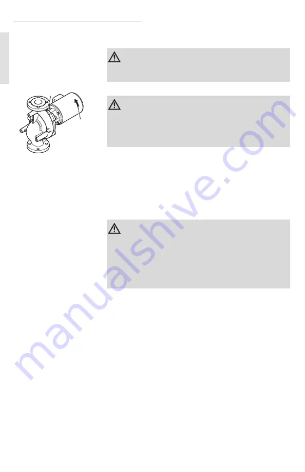
6.3 Fill and ventilate

Ventilate

1.

Open air vent valve (1) 1/2 turn, do not remove

.

2.

Completely open suction side and discharge side isolation 
valves.

3.

Wait until the liquid has exited the ventilation opening and 
until bubbles no longer form.

4.

Tightly close the ventilation opening.

Avoid cavitation

5.

Ensure that the minimum pressure stipulated in the product 
catalog is present on the suction side.

Check direction of rotation

6.

Check the motor's direction of rotation by briefly turning it 
on. The direction of rotation is correct if the fan or other 
visibly rotating parts of the pump are rotating in the direction 
of the arrow (2).
On three phase only, if the direction of rotation is incorrect, 
have an electrician correct it by swapping two phases.
For single phase applications, to change direction of the 
motor please follow the directions supplied with the motor. 
If there is not arrow on the motor run the pump, note pres-
sure, reverse rotation and recheck pressure. The rotation that 
produces a higher pressure is the correct rotation (for clarifi-
cation contact WILO).

7.

Turn on the pump for test operation and observe whether it 
is pumping correctly. If necessary, ventilate again until a 
sufficient pumping result is achieved.

Caution: Damage due to dry running!

The pump may never be allowed to run dry. Dry running destroys 
the mechanical seal.

1

2

Warning: Danger due to hot liquid under pressure!

Extreme caution must be used when venting systems that have
elevated temperatures and/or dangerous fluids. Maintain suffi-
cient distance from the air vent opening, wear suitable clothing 
including protective glasses/facial protection and gloves.

Caution: Damage due to cavitation!

Failing to maintain minimum pressure on the suction side can to 
lead to cavitation accompanied by noise.This can damage the 
pump. This minimum inlet pressure depends on the operating 
conditions and the duty point of the pump and must be calcu-
lated accordingly. Please contact WILO or your WILO distributor 
if this further information is required.

Summary of Contents for Cronoline

Page 1: ...Installation and operating instructions Wilo Cronoline 2 069 148 Ed 02 2007 05 11 Kothes...

Page 2: ...e page 8 Installation page 8 Maintenance and Repair page 13 Screw torques page 18 Technical data page 5 Electrical connection page 10 Mechanical Installation page 8 Ventilate page 12 Check direction o...

Page 3: ...Mechanical Seal Air Vent 4 Shaft 5 Lantern 6 Coupling guard 7 Coupling 8 Motor 9 Motor bolt 10 Condensate drain connection only in some models 11 Condensate drain connection 12 Volute Bolt 13 Suction...

Page 4: ...Safety sticker Safety stickers are located on the motor giving important instructions on how to handle the pump The instructions on the safety sticker must be strictly obeyed Qualifications The pump...

Page 5: ...r and secure against reconnection Never switch on the motor when the pump housing is open or the coupling guard is missing Never operate the pump without the coupling guard High Deadweight The pump ha...

Page 6: ...rom 4 F to 250 F 20 C to 120 C Max permissible liquid temper ature range with high tempera ture seal at 175 psi 12 bar from 4 F to 250 F 20 C to 120 C at 165 psi 11 bar from 4 F to 285 F 20 C to 140 C...

Page 7: ...is driven by an electric motor according to the NEMA standard Assembly For pumps up to an output of 20 HP the flanges are designed such that the pump can be mounted without additional support For pum...

Page 8: ...6 Installation 6 1 Mechanical Installation Caution Damage due to incorrect packaging If the pump needs to be transported again at a later date it must be securely packaged for transit Use the origina...

Page 9: ...ards Fig C In the case of installation with horizontal motor B the air vent valve must point upwards 3 If necessary disassemble the motor and rotate Page 14 The electrical terminal box may not point d...

Page 10: ...the cable such that no condensation or spray water can run into the cable screws Fig A 6 Connect grounding cable 1 2 Caution Damage due to overheating For insulated piping systems only the pump volut...

Page 11: ...ion when connecting to an automatic pump control device Comply with respective installation and operating instructions when wiring to automatic pump control device DDC or Building Management Systems B...

Page 12: ...w on the motor run the pump note pres sure reverse rotation and recheck pressure The rotation that produces a higher pressure is the correct rotation for clarifi cation contact WILO 7 Turn on the pump...

Page 13: ...to electrical shock Touching live components can be fatal Only qualified electri cians may work on the electrical system Prior to any mainte nance work disconnect the pump from the power supply and se...

Page 14: ...ate drain 5 If motor is in horizontal installation position support the motor or secure it from falling with a crane and a suitable hoist 6 Remove screws 1 and remove coupling guard 2 on both sides 7...

Page 15: ...keoutlanternunit 2 withcoupling shaft mechanicalseal and impeller using suitable lifting equipment and remove from pump housing Remove impeller 14 Loosen impeller fastening nut 1 counter clockwise 15...

Page 16: ...s a lubricant 7 Insert a new O ring 2 in lantern groove 8 Carefully insert pre assembled unit consisting of coupling and shaft 2 into lantern 1 9 Hold coupling and shaft in place 2 in lantern 10 Press...

Page 17: ...ighten coupling screws slightly at first until half coupling shells are lying on spacer disks 24 Then screw coupling together equally Torque Page 18 Specified distance of 0 197 inches 5 mm between lan...

Page 18: ...Shaft Stainless steel 3 8 22 30 1 2 44 60 5 8 74 100 Pump housing lantern SAE Grade 5 5 8 75 100 Adapter flange lantern SAE Grade 5 5 16 18 25 1 2 44 60 Lantern motor SAE Grade 5 3 8 26 35 1 2 44 60 5...

Page 19: ...an cover for dirt dust accumulation and clean if necessary Check ambient temperature and if neces sary ensure an ambient temperature 105 F 40 C by forced ventilation Pump runs at reduced capacity Inco...

Page 20: ...LC 1290 North 25th Ave Melrose Park IL 60160 USA Phone 866 945 6872 WILO USA FAX 403 277 9456 Wilo Canada Inc Bay 7 2915 10th Ave N E Calgary Alberta T2A 5L4 CANADA Phone 866 945 6236 WILO CDN FAX 403...

Reviews: